This page introduces optocouplers to hobbyists, etc. It really doesn't matter if you are using an Arduino, a Raspberry Pi, a PIC.... optocouplers can be useful to you. This page concentrates on how optocouplers can help in low voltage digital circuits.
Optocouplers are elegant little devices with very little about them to "go wrong". And they are "fail-safe": If something goes wrong, your system won't work, but things should just stop rather than moving in a bad direction. Consider your car: The engine is "fail safe". If it dies, you just drift to the side of the road and stop. Your brakes are not fail safe. They fail, and you're in trouble.
In this page, we will consider how optocouplers can be useful both on inputs and on outputs.
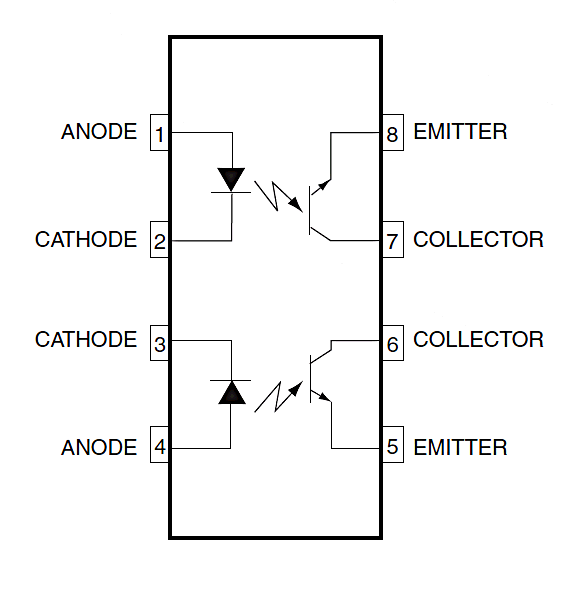
Simple optocouplers consist of an LED and a photo transistor, embedded within a bit of plastic. Often that "bit of plastic" will hold more than one optocoupler. The following eight pin DIL package would have two independent optocouplers in it, for instance.

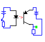
The LED and phototransistor are not "connected", but when the LED is on, light from it strikes the phototransistor inside a little pocket of air inside the opaque "bit of plastic", and the phototransistor conducts. (In fancy optocouplers, the phototransistor may be replaced by something else that "switches on" when the LED illuminates it.) In the following, I've drawn the optocoupler in black, things you might attach to it in blue. At the green blob, you will get a high voltage or a low voltage, depending (indirectly) on the state of the LED, itself determined by the state of the switch.
You won't see the light from the LED... it will be inside the "bit of plastic."
You might well set up an optocoupler as above with an input line of a microprocessor, e.g. an Arduino connected to the green blob. (We'll talk about sending signal out of a microprocessor though an optocoupler later.)
Some time ago, I created a small PCB to "carry" MCT61-type optocouplers...
The link will take you to the details, including prices and how to order.
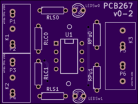
Since that time, I have created a "bigger, better" four channel opto-coupler board, with (optional) LEDs so the user can see the state of inputs and outputs at a glance.
(I have discussed putting optocouplers on outputs further down the page.)
A simple reason? You could use an optocoupler if you were uncertain about what you are doing. If you weren't sure that circuits you wanted to connect to an input were "safe" for your relatively expensive microprocessor, you could connect the microprocessor to the optocoupler as above, and use your circuit to turn the LED on and off. If you did that, then many mistakes you could make would only ruin the quite cheap optocoupler. The Bad Stuff won't jump across the gap between the LED and the photo-transistor. If you've used a socket for the optocoupler chip, always a good idea, then replacing it only takes a moment.
That's one simple reason for using an optocoupler.
Sometimes the thing you want to use to make the input high or low isn't "cooperative". Perhaps it is part of a circuit operating at some voltage which doesn't suit the microprocessor? No problem. The voltage can be whatever is handy... you adjust the resistor accordingly. (See my guide to LEDs for details.)
Of course, the thing that turns the LED on and off won't always be a simple switch.
Even when it is, and even if the voltage could be 5v, if you wanted, 5v is not always a good choice. Suppose the switch is going to be part of an anemometer on the roof of a building? Pushing 12v through those long wires might make better sense. And, as lightning storms pass through, those long wires will be an antenna.... induced voltage spikes could come down them. Would you rather an optocoupler was fried, or your microprocessor?
If that mention of an anemometer tweaked your curiosity, I have pages about weather monitoring for you.
Let's consider the right hand half of the circuit above. It won't always be just as shown, with the green blob as the "connect to microprocessor" point. But for simple work with, say, an Arduino, the circuit is nearly what you would do. For the Arduino, things would be really simple: you would merely connect the "top" of the transistor to one of the Arduino's inputs, the bottom to the Arduino's ground, and turn on the internal pull up resistor on the Arduino's input.
N.B.: To get the benefits of the coupler (isolator), you can't use the Arduino's power to activate the LED. You need separate power on that side. Furthermore, don't think "Oh, we always connect all the grounds." In this circuit, you DON'T connect the grounds. (There are two: one on each side of the air gap.)
(I have discussed putting optocouplers on inputs further up the page.)
You know how to turn LEDs on and off with your microprocessor, I hope?
The LED inside an optocoupler isn't in some way "special". Remember to include the usual current limiting resistor, and you can switch the optocoupler's LED on and off... and thus, indirectly, switch anything else on and off.
This will primarily be useful to beginners who want an extra layer of "safety" between their possibly-badly-designed circuits and their microprocessors.
There are ways to use a transistor to "switch" things safely which can't be directly switched by a microprocessor output. But if you are not sure how to do that, use an optocoupler.
The phototransistor in the optocoupler is only a tiny little thing... and it can't usually switch a heavy load, e.g. bright lights, motors. But you can use it to operate the coil of a small relay, and the contacts of the relay can, if you buy the right relay, switch big loads.
A word about household, or "mains" electricity, e.g. 110 volts AC, or 230 volts AC. Stay away from it until you've had proper training. There are Ways To Go Wrong which you don't want to encounter, and may not see coming. And errors can lead to death and destruction... literally.
You can buy a basic two gate optocoupler from Digikey for about $1, but that's just an example. There are many, many suitable devices out there. Be careful with the pin-outs... there are two commonly used layouts, each with its own strengths.
Another choice: There's a nice little package with 4 slightly fancy optocouplers in it. They are "fancy" only in that each optocoupler has two LEDs, one facing easy way, so that both AC and DC signals will turn the output on. One example of this design is the nattily named "PS2505L-4", from NEC.
You might think that it would be okay to put the LED side of an optocoupler, with suitable resistor, across an AC signal, and let it just "throw away" the negative half of each cycle.
The light emitting DIODE will indeed block a "reverse" flow of current... up to a certain, not always very high!! voltage.
If you are putting an optocoupler intended for DC signals on an AC signal, it may well work... but check the datasheet. You can always add an external diode, meant for blocking a voltage, if you want to go with the "half wave is enough" "answer". Be advised, though: If you are "watching" the output with a microcontroller, say an Arduino, it checks the output so briefly that it may not see the "on" parts" of the signal, even when the AC is present.
There are opto-couplers made specifically for AC inputs. Simple, really... there are two LEDs inside the chip, so one lights when the current flows one way, and the other flows when the current reverses.
If you want to see if the phototransistor is conducting when you pass a current through the LED, you can use a multimeter, set to measure resistance, or to "beep" when the mutlimeter's leads are shorted.
Certainly for the "beep" test, and also, I suspect, for the resistance measure, you need to connect the leads to the phototransistor "the right way around". To measure the resistance, or to make the meter beep, some current must flow. "Ground" lead of multimeter to the pin the arrow in the phototransistor points towards.
I have started a page on how to choose the right resistors for your particular circumstances. That page was quite "rough" when I created this link to it. If you find the page NOT rough, by the time you go there, please send me an email saying "You need to update the remarks at bottom of Aru\ec\ec1optoiso.htm about the page about getting the resistors rights." (Thanks!)
I hope that helped? Do please write in and tell me if bits were unclear, or you would like more help with optocouplers
![]() Page has been tested for compliance with INDUSTRY (not MS-only) standards, using the free, publicly accessible validator at validator.w3.org. Mostly passes.
Page has been tested for compliance with INDUSTRY (not MS-only) standards, using the free, publicly accessible validator at validator.w3.org. Mostly passes.
AND passes...

....... P a g e . . . E n d s .....