 Recommend at StumbleUpon
With a "typical" small red or green LED, and a 5v supply, you need a current limiting resistor of about 270 ohms to have only 11.6 mA current. The LED will probably glow at least faintly with a resistor as large a 1k. There's no harm in trying a large resistor. Worst case: It won't glow! If your resistor is too small, even if you don't fry the LED (which you can do), you may overtax the circuit driving the LED.
This quick answer cannot be relied upon, because it assumes too much. It assumes that your idea of a "typical" LED is my idea. It assumes that the brightness you get from a certain current is the brightness you want.
And be warned: you cannot use simple rules like, "He said 270 ohms would give an 11 mA current, so 540 ohms "should" give a 5.5 mA current." Again, broadly speaking, you may find that 1k gives 3.3mA, 220 ohms gives 14 mA... but it depends on your LEDs.
A wise person once said "Choose two: fast, good, easy". If it is fast and easy, it will rarely be good. If it is easy and good, it will rarely be fast. And so on.
This essay dips down to "baby steps" in places. If you are already past "baby steps", please read on anyway?... More advanced material follows, but I want the material to be accessible to everyone. I have also published a First steps with LEDs page if you are new to electronics, and just want the highlights for now. I've also done a page about using LEDs aimed primarily at Arduino users which anyone using microprocessors might find useful.
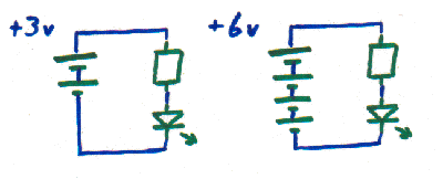
The following will suffice for making some preliminary points:
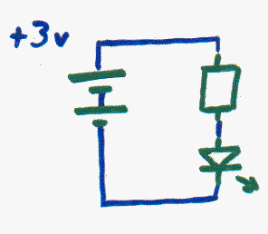
They show LEDs
![]() , resistors
, resistors
![]() , and simple batteries. The first circuit's battery has two cells
, and simple batteries. The first circuit's battery has two cells
![]() ; the other has four.
; the other has four.
![]()
The two cell battery provides 3 volts, the four cell battery provides 6 volts. A cell is what we usually call a "battery. "AA" cells would be fine for experiments with LEDs. We will talk about other options later.
The LEDs in the circuits will be glowing nicely if the LED has not been connected backwards and you have chosen the right resistor. More on the latter in a moment.
A detail: It doesn't matter if the resistor and the LED are in the other order....
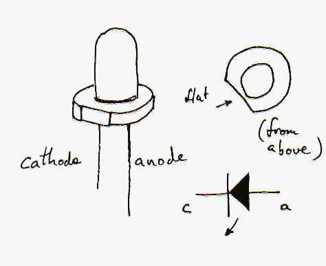
Good news: If the LED is connected backwards, no harm will come to anything. If you're sure everything else is right, just turn the LED around and it should light up. To be honest, I usually get the LED's orientation right by trial and error. If you have an LED with a slight "flat" on one side of the case, or with one leg slightly longer shorter than the other, then that side or that leg will probably be the cathode, i.e. the leg that should be connected to the "bottom", or more negative side of the place the LED goes into the circuit.
If the battery, or other source of voltage for the circuit is too "big", or the resistor is too "small" (for the voltage you are using), it will Not Be Good. Worst case: You'll damage the source of the voltage... which may be something expensive! Bad case: You'll destroy the LED. (They're cheap, but you may not have another one to hand.) But that's gloom and doom. You rarely need to Go There. (You sometimes get away with things you should not, too... but don't depend on it!)
So how to get things right? Start by using the right terms. The important parameter of a battery is the voltage it delivers. An AA "battery" (cell) brightly declares that it delivers 1.5 volts. So four AA cells connected in series, as in the second circuit in the first diagram, should deliver 6 volts.
There's a catch. A battery made of four AA cells will only deliver 6 volts if you don't ask too much of it. Connect one LED, with the right resistor, and you will get 6 volts from the battery. Attach 300 LEDs, even with the right resistors, and things won't work as they "should". We'll come back to this concept later. For now: The voltage from the battery can be assumed to be 6 volts.
Voltage is the reason electrons move when there is a complete circuit for them to travel around. It is dangerous to call voltage a "push" or a "power" or lots of other words you may have encountered. Just bear with me, press on. Consider "voltage" "done" for the moment. We have just two other words to deal with: current and resistance.
Current is how many electrons are flowing past a given point in the circuit each second. It is measured in amps. (But don't infer that a current of one amp means that one electron per second is flowing. The idea is as simple as that, and we don't need to go into the actual, tedious, numbers.) Current is why things happen. Bulbs are brighter, electromagnets are stronger, etc.
Resistance is the opposition to the flow of the electrons. In the circuits above, the resistors are there just to create some resistance. Why do we need resistance? If there was no resistance in a circuit, the current flowing would become extremely high. In theory the wires would become dangerously hot because of the extreme current, but in many cases other factors would intervene and the voltage would drop down and that would limit the current.
Most electronic devices have resistance, but the resistance of LEDs is only slight, and it doesn't obey some of the usual rules. Hence the need for the discrete resistor in the circuits above, and this essay!
How much current will flow is usually a simple matter... if LEDs, diodes, transistors are not involved. You look at the voltage present and you look at the resistance to the flow of the electrons, and with a little simple arithmetic you can calculate the current.
In our circuit, we have a 6v battery driving an LED, with the current also passing through the resistor. If our resistor is too small, the current will be too high. As I said: worst case: We burn out the LED. Bad case: We will exhaust the battery sooner than we needed to. (A "small" resistor is one with a low resistance. I'm not speaking of its physical size. As for physical size, which is largely determined by the resistor's "wattage", a quarter watt resistor will be fine for most LED work, or even an eighth watt resistor. More on this other parameter in the appendix.) If the resistor is too large, the LED will not be very bright, or it may not be glow at all, even though there is a slight current passing through it.
Here's how to calculate the right value for the resistor: Start, if possible, by looking up the "forward drop" and "typical operating current" for the specific LED design you plan to use. If those numbers are not available, we use typical values, and see what we see, and make adjustments as seems necessary. (If you have to make a guess at the LED's characteristics, try a slightly "too large" resistor first. Measure the voltage drop and assess the brightness/ current, and adjust the size of the resistor accordingly.)
There's more advice on "typical" values at www.theledlight.com/LED101.html, but, for an "ordinary" red LED, you won't usually go far wrong if you assume a forward drop of 1.8 volts. For a green LED try 2.1 volts, and for a blue LED use 3.3.
If you are using guesses to choose your components, start with a guess that 20mA will be the "right" current. If the LED isn't bright enough, and if you can detect no heat build up, reduce the size of the resistor you are using.
When looking up the "right" figures for an LED, be sure to use something around the LED's typical operating currents. Most datasheets will also tell you the maximum current the LED can tolerate, but routine operation at that current is not sensible.
Remembering that we are going to use a 6v battery, let's say that our LED has a forward drop of 1.8 volts, and a typical operating current of 20mA. (These are good values to try for "ordinary" LEDs.)
Start with the total voltage drop across the combined LED and resistor: 6 volts. Subtract the forward drop, which leaves us with 4.2v. Now ask "What resistor would it take across 4.2v to result in a current of 20mA?"
In order to answer questions like that, you can always start with the (to me!) most intuitive statement of Ohms law:
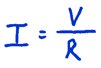
The current (abbreviation "I"; measured in amps) will be equal to the voltage (in volts) divided by the resistance (in ohms). E.g. You will get a current of 4 amps if you have 20 volts acting on electrons flowing though a circuit which has a resistance of 5 ohms. Those voltage and current levels aren't often found in the electronics "play" of hobbyists, but they illustrate the simple form of Ohm's law.
Resistance is often expressed in "k", kilo-ohms, thousands of ohms. People call a 10 kilo-ohm resistor a "10k" resistor)
Once you have Ohm's law clear in your head, with some simple mathematical skills you can work forward to things like "R (in kilo-ohms) = V (in volts) divided by I (in milliamps)".... or you can work things like the following out by your own mathematical means, however you wish, as long as you get an answer of 210 ohms!)
When the voltage involved is 4.2 volts, as it is in the circuit we were choosing a resistor for a moment ago, then the resistance you need to get the 20 milliamps we said we wanted as the current flowing is 0.21k (kilo-ohms), which is the same as 210 ohms. A 210 ohm resistor is hard to come by, but 220 ohm resistor are easy to buy, and should be just fine.
(By the way... why do I insist on capitalizing the "W" on "Watts", but not the "o" on "ohms"??? I don't know. Just seems right, even if it is inconsistent. (Both units of measure were named for a man; both "should" be capitalized.))
As I said before when discussing the general case: If I were working with a simple red LED of unknown properties, and 6 volts, I would initially hook it up with two or three 220 ohm resistors, in series, and see what that looked like (maybe even measure(!) the current and voltage drop). If it were a bit dim, or the current a bit low, I'd gradually reduce the resistance until I was getting a good result.... without heat buildup in the LED. With a measured voltage drop to work with, my second resistor choice could be by calculation. (The voltage drop across the LED is constant, within wide limits, remember.)
So what was so hard about that? Not too awful. But!....
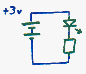
Now consider the first circuit in the diagram at the top of the page. We have half the voltage in this circuit, but still just one LED. So we need half the resistance to see the same current, the same brightness, right? Not right. Well of course not... we didn't include the resistance of the LED in our calculations. We just work out what it was contributing in the 6v circuit, and re-do the calculation. Right? Wrong again. The LED doesn't "behave nicely". It doesn't have a constant resistance you can just plug into calculations the way you plug the resistance of a resistors into calculations.
So we just proceed as we did before.
Start with the total voltage: 3v. Subtract the forward drop of the LED: we said our LED's forward drop is 1.8 volts. So the resistor is "fighting" 1.2 volts. We want (because of the LED we have) 20mA of current, so this time we need.... 1.2 divided by 20= 0.06 k ohms = 60 ohms.
If you are buying LEDs out of a catalog for a particular job, you are allowed to choose between all sorts of things. Price and color, of course. Brightness.... here's a good case of "more is not always better"! If you want to drive numerous bright LEDs, you may run into the need to interpose additional circuitry between your LEDs and whatever you are using to control them. If you are running on batteries, they will be exhausted faster. LEDs come in different shapes, and, related (but not as obvious), they come in different packages which either emit a relatively narrow beam of light, or spread the light across a wider angle of view. You can buy LEDs with built-in current limiting resistors, but, as we have seen, the resistor you need depends on the voltage you are applying, so the built-in resistor will only be "right" for one voltage. I... resist (sorry)... the temptation to buy LEDs with the built-in resistors so that I won't fall to the chance of accidentally inserting a resistor-less LED into a circuit with no other resistor.
Earlier I said: "Connect 1 LED, with the right resistor, and you will get 3 volts from the battery. However, you must not imagine that you can attach 300 LEDs, even with the right resistors, and have things work as they should".... so how much is too much?
First: How are the LEDs connected? The options are "in series" and "in parallel". The upper circuit in the next diagram has the LEDs in series, and the other has them in parallel.
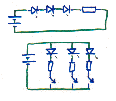
You might want to use the series arrangement in some circumstances. In such cases, for three LEDs, you would do the calculations as if you had one LED with three times the forward drop of one of the LEDs. For four LEDs, four times the voltage drop, etc.
You are more likely to be connecting the LEDs in parallel. In the diagram, I've shown switches which would allow you to turn just some of them on. In real life, you would control which LEDs are on with electronics.
How much is too much? The parameter which must not be exceeded is the power used. That's "power" as an electronics engineer would use the term.
Multiply the current through each LED by the total voltage across the battery to know how much power you are using. Multiply the current through the LED times the voltage drop across the LED to know how much of that power is being dissipated within the LED.
Each element of your circuit will have a limit on the power that is safe and satisfactory for it. In some cases, you will see the limit expressed in amps, i.e. "the pin can handle 50mA" but in those instances, there will be an implied voltage value. For instance, your LED's data sheet may well tell you that a certain current level is the maximum permitted. Because (within the acceptable operating range of the device) the voltage drop across the LED is constant, the manufacturer can take this shortcut when telling you the LED's limit.
If we've chosen a resistor to make 20mA (milliamps, or thousandths of amps) flow past each of the LEDs in the circuit, the power draw for each path is 60 mW (milliWatts) (20 x 3) The total drain on the battery for the parallel circuit would be 180 (3 x 60) mW per unit time. E.g. if you ran the 3 LEDs for two hours, you would have used 360 mWhr of the battery's capacity. (An alkaline AA battery can supply about 3000 mAh if it is only subjected to a light load, but at loads of around an amp, the capacity might be as little as 700 mAh. (Thank you Wikipedia for that.)) Don't think "Ah! Two cells, two times 3000mAh." You could get 6000mAh from two AA cells if you wired them in parallel.... but then you would only have 3v.
There are limits. Batteries and power supplies stop working as they are "supposed to" if you set up a circuit which would, if the battery continued to supply its rated voltage, result in an excessive (for the battery) current. If you are using a microcontroller to drive some external devices, say LEDs, you must respect the design limits of the microcontroller, too. It may be damaging to the microcontroller to source or sink more than, say, 40mA per digital output, or more than a total of 200mA overall. So if the microprocessor has 10 digital outputs, you could have 5 external devices with 40mA flowing through each of them, but not more than five devices like that turned on at any given moment. (You wouldn't exceed the "per pin" limit with 6 such devices, but you would exceed the "overall", or "package" power dissipation limit.) (Note that here we have taken the shortcut of expressing the power limits, which should be in mW, in mA. We can do this because we know the voltage at which the microprocessor will be operating.)
The numbers I gave (40mA/pin; 200mA overall) are the absolute limits for an Atmega328 based Arduino. I could not find guidance, even in the chip's datasheet (.pdf), on acceptable ordinary operating levels. 40/200 are the maximums allowed.... but if you run one at 40/200, don't expect it to last as long, or be as reliable as one not pushed to the max.
The Arduino, by the way, is a very neat little package for hobbyists. Not too expensive, not too complicated, not too new (but it does evolve to use new opportunities)... and plenty of power, and a good user group behind it. I've done a little Arduino page where I wax more extensively lyrical about its merits.
So far we have talked about lighting LEDs with batteries, even though I suspect that most readers will be using semiconductors, perhaps a microcontroller, perhaps an Arduino to light their LEDs. Fear not! Everything you have struggled through so far is still Good To Know. Here's the rest of what you need....
You can hook your LED to a digital output pin two different ways...
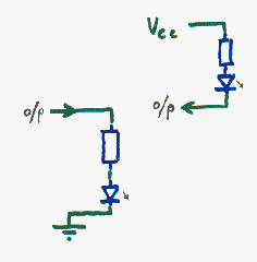
Note: In BOTH cases that you need to use a digital OUTPUT (or a microprocessor (e.g. Arduino) pin configured as an output in cases where pins can be inputs or outputs). Novices may find it strange that in the right hand circuit, the electricity is flowing into an output, but that is correct. (Your idea of what an "output" is might need some adjustment. See my introduction to Inputs and Outputs.)
In the right hand circuit (above), the electricity flows from the circuit's Vcc, (i.e. the positive voltage being "fed into" the chips, often 5 volts) through the current-limiting-resistor and the LED, and then into the semiconductor's output.
In the left hand circuit (above), the electricity flows from the semiconductor's output, through the current-limiting-resistor and the LED, and then to "ground", i.e. the "wire" with zero volts to which many things get connected.
In the left hand circuit, the LED lights when the output is made high. The output is said to "source" the current. In the right hand circuit, the LED lights when the output is made low. In this case, the output is said to "sink" current.
From the programmer's perspective, it is perhaps most logical to wire things as in the left hand circuit, but some digital devices are better at "sinking current", i.e. making the LED light by a circuit of the right hand type, than they are at "sourcing current" which is what you're asking the output in the left hand circuit to do.
Which is the best arrangement for your needs will depend on the device in your circuit providing the outputs. I tried to see what the situation would be if you happen to be using an Atmega328 based Arduino. I discovered that the pins, when configured as outputs, should never source or sink more than 40mA, but I could not find guidance, even in the chip's datasheet (.pdf), on acceptable ordinary operating levels, so on electronic grounds, I can't tell you if one of the other is best with an Arduino. The datasheet also said that the current through Vcc or Ground should not exceed 200ma.
It is easy for programmers to make and use subroutines called "turnLEDon" and "turnLEDoff" to "bury" the electronic details. (And programmers should probably do this.) (A subroutine called "LEDOnOff", with two parameters... one for which LED (of several connected to the controller), and the other for whether it is to be on or off is a little fancier, but not much. And it is very useful when you are ready to handle the "complexity".)
We already talked about the main characteristic of a resistor: its resistance ("ohmage"- not a "proper" term, just one I've used here to reassure you). In a second I'll cover some other characteristics, but first I'll introduce you to a component which is useful if you have several LEDs in your design. It is called a "resistor array". It is a little package containing multiple resistors, built like this....
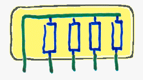
The resistor array shown above has four resistors in a single 5 pin package.
Especially if you are making a PCB for your project and it uses multiple LEDs, consider using these neat little components.
By the way.... don't hope that you can get away with....
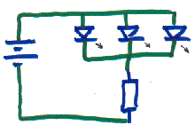
The brightness of the LEDs won't be consistent. The mathematics of the reason is pretty simple. I'll leave the rigorous analysis as An Exercise for The Student. Just recall that the voltage drop across the LEDs will be constant... and remember that if more current were to flow through the resistor, "collected up" from the multiple paths through the multiple LEDs when more are turned on, the voltage drop there would increase, which would decrease the voltage drop across the LEDs... but the voltage drop across the LEDs won't change, so something has to give, and it will be the current flow. So when different numbers of LEDs are lit, they will light with different bright nesses.
You can buy really tiny resistors, especially if you go to surface mount devices. Now, you wouldn't expect a tiny device to successfully carry much current, would you? So resistors have power ratings. To be sure you haven't chosen an inadequate resistor, multiply the maximum current which will flow through that resistor times the voltage drop which will occur across it.
We discussed previously how to determine the right "ohmage" (resistance) for the resistor in the above to make the current through the circuit be 20 mA, which, for the sake of this discussion we will say is right for our needs. We'll also assume an LED which has a 1.8v voltage drop. So we are looking at an 1.2 volt drop across the resistor. 1.2 x 20 gives us 24. The units would be milliwatts, so a quarter watt (250 mW) resistor would be much more than enough. Even an eighth watt resistor would be fine... but I tend to avoid them because...
While we're at it, we might as well look at another factor in resistor selection. You can buy "carbon film" or "metal film" or other sorts of resistors. They all have their pros and cons... but for limiting the current flow through an LED, the cheapest sort will be just fine.
It seems that many devices with bright LEDs on them use a "trick". While the LEDs appear to be constantly "on", they are in fact being pulsed rapidly on/off/on/off/etc. I suspect that the reason for the extra complexity is that eye perceives the brightness as being higher, even though the LED is off for half or more of the time. It may be that if you pulse the LED, it can be brighter when it is on than it could be if it weren't for the off periods. It may be to do with minimizing the drain on a battery. It may be that your eye/brain is drawn to a "flashing" light, even if the flashes are too rapid for your senses to perceive their existence. If you see something, and wonder if it is one of these "flashing" LEDs, sweep your eyes past the light in question. If it is flashing, instead of a blur where the light was, you'll see a line of dots or dashes. However much you learn, there is always more!
![]() Page tested for compliance with INDUSTRY (not MS-only) standards, using the free, publicly accessible validator at validator.w3.org
Page tested for compliance with INDUSTRY (not MS-only) standards, using the free, publicly accessible validator at validator.w3.org
....... P a g e . . . E n d s .....