This page describes a small PCB you can buy, to permit the simple and robust hook up of an opto-isolator (aka opto-coupler) in whatever project you have that needs one.
(Quite a while after creating this PCB, I created something similar... this time an opto-coupler (opto-isolator) protectiion for four channels... and after that, I created another board, PCB277, for the same chips the board that is described below is for. PCB277, the newer newer dual channel board, is probably better than the one below, but they both have their merits!)
If you don't know a lot about optocouplers yet, I have a page for you!
Eventually, you will be able to order the PCB from OSH Park, about $3.30 inc p&p... but the minimum order is 3 boards.(If you need this board NOW, contact me.) If there is interest, I will consider selling kits with a board and the parts to populate it.
If you want to remember this for later, or share the URL, http://tinyurl.com/OptoCouplerBreakout is another way to get here.
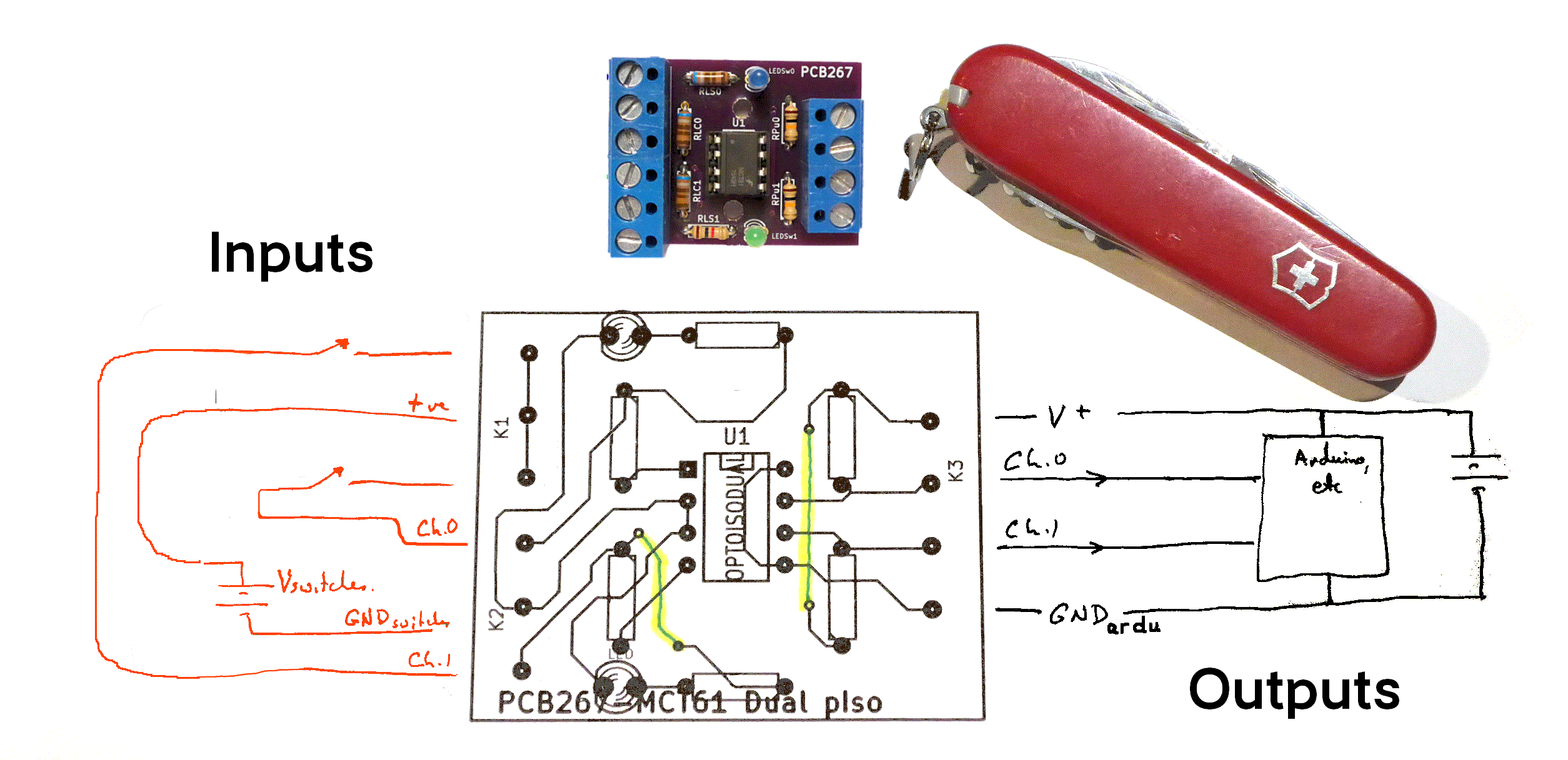
The following image was created using the prototype. The OSH boards are professionally made...
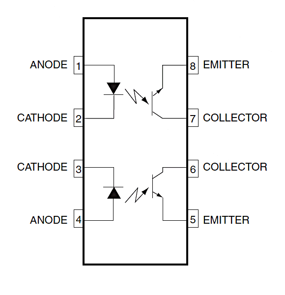
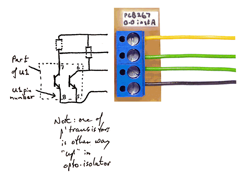
The PCB carries one MCT61-type opto coupler...
...
( v v (more further down page) v v )
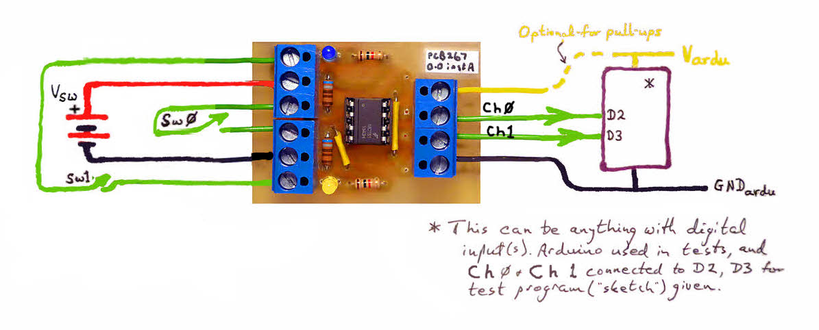
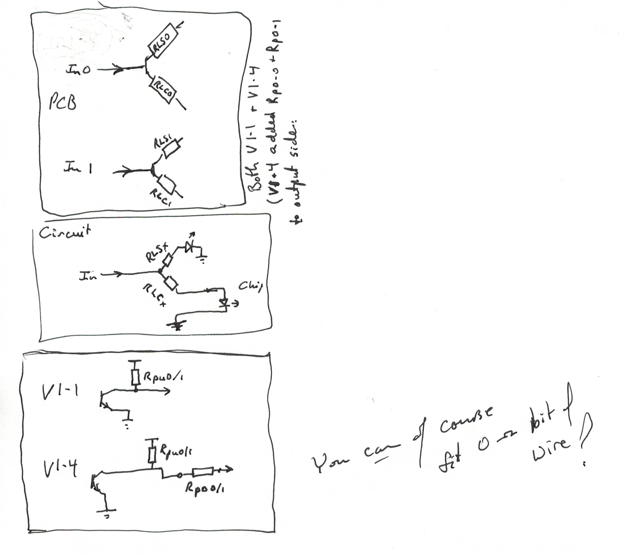
As it stands, the PCB is fine for two separate inputs, with the outputs feeding two inputs to the next module in your design. It is assumed that the outputs will be driving two inputs which share a common ground.
Another use for the board is to take a single input, and derive two independent outputs from that... outputs to feed circuits which do not share their grounds.
For that use, you would feed the same input to both the Ch.0 and the Ch.1 input to PCB267, after making the following modifications to the board. (This relatively simple solution does mean that you lose the pull up resistors. (They are easy enough to provide at the other end of the wire from the output of PCB267 to the input of whatever you are driving with it, aren't they?)
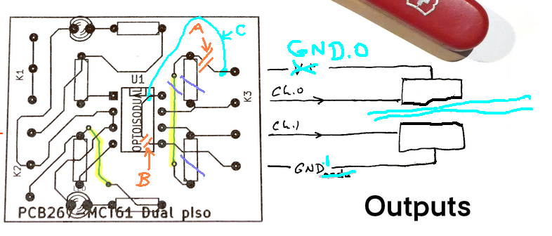
The diagram above is trying to say....
A Cut this track/trace
B Cut this track
C Solder a jumper wire between the points shown
Purple. lines across resistors and link You can leave out the resistors and cut the track on the top side of the board... if you wish. There's no harm in leaving them in place, if they are already there. (As the track will be, of course.)
At the right, I have changed the labelling of the signals to reflect their new roles.
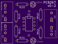
This is an attempt to help you with what resistors on the board do what jobs...
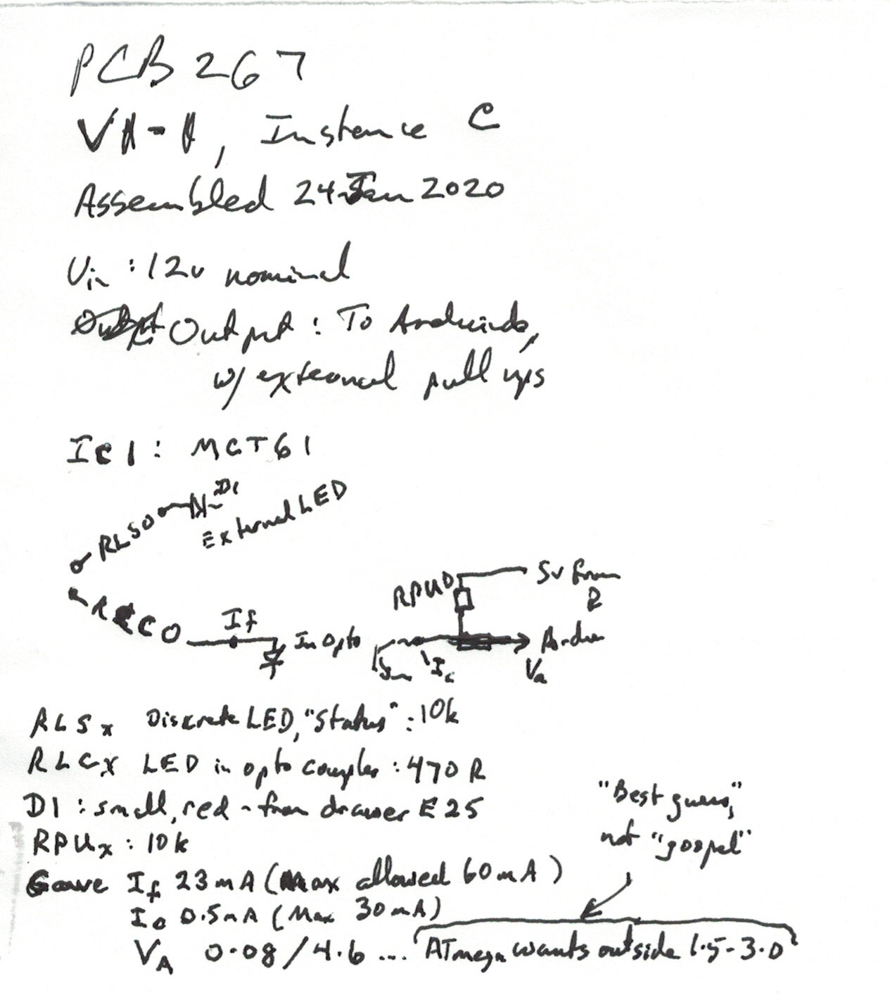
Here are some values I used in populating the board for a specific .task..
![]() Page tested for compliance with INDUSTRY (not MS-only) standards, using the free, publicly accessible validator at validator.w3.org. Mostly passes.
Page tested for compliance with INDUSTRY (not MS-only) standards, using the free, publicly accessible validator at validator.w3.org. Mostly passes.
AND passes...

....... P a g e . . . E n d s .....