This page is intended to help novices. There are no major, advanced level concepts here.
If you are still reading: Please- be careful. If you half understand what is here, and apply it a little incorrectly, it is easy to damage your Arduino, or whatever microprocessor you are trying to apply these ideas to. The good news, however, is that sometimes you will fry only the one port you connected the wrong thing to.
UPDATE: 8/19: Since writing most of this page, my understanding of transistors has improved. I have a new (8/19) page about using NPN and PNP transistors as switches... relevant to much of what follows.
I suspect that the techniques discussed here need very little modification for use with 3v3 microprocessors... but I myself am too new to those to give informed advice. (Also, everywhere in this you see "12v", you can, with minor changes, make it 9v or 24, etc... but note: It needs to be DC, for the techniques here, and I would not advise novices (or intermediate hobbyists!) to try to work with "household" electricity, i.e. 110 or 240v, AC.)
If you are at all worried that you might be making a mistake, the things we are going to do here can be done with confidence by using opto-isolators (aka opto-couplers). And, in that scenario, you can keep the ground for the high voltage side of things separate from the ground for the microprocessor's power.
So... a first set of warnings and alternatives delivered, here's how you can do it with transistors.
Here is a safe way to drive a 12 volt device from a 5 v Arduino. The diagram specifies an IP Cam as the "12 volt device". It could be something else.
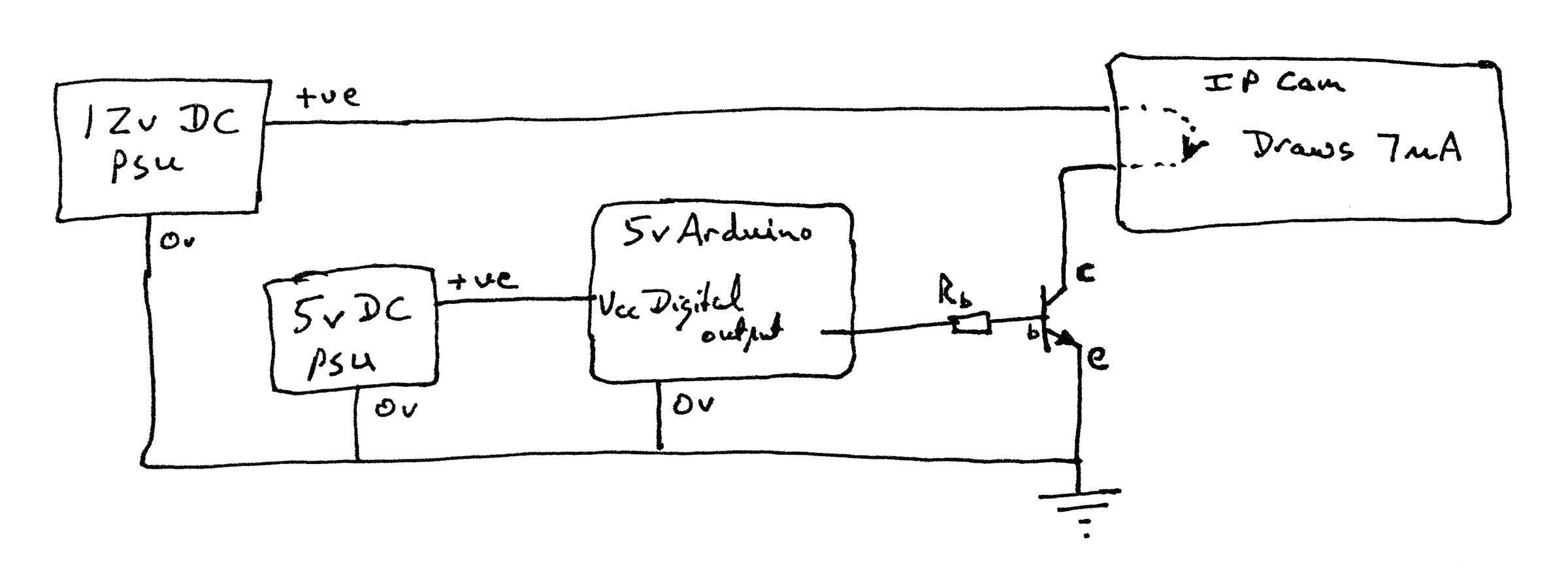
Going through the elements of that diagram...
On the right, an IP camera with two terminals labeled "DI+" and "DI-". With the IP cam in question, if you put 12v on DI+ and connect DI- (directly or indirectly) to ground, (and you've configured the camera and an FTP server!) then the camera sends what it sees to an FTP server.
Note well: not all IP cams want more than a simple switch on their digital "input", and those that want a voltage don't always want 12v.
The camera is relevant to this essay only as an example of something that operates on 12 volts.
Many novices get confused about the current that a device "draws".
Before you try to control whatever you want to control, hook it up directly to a 12v source, and measure the current that flows. The device doesn't "make" that current flow, it doesn't, literally, "draw" that current, even though electronics designers use "draw" in that context. The current is the result of the voltage (12v in this case) and the resistance of what you are connecting....
As long as you Don't Ask For Too Much.
Look at the tiny writing on the case of any "wall wart" you may have. (Or other power supply). It may say "12v DC", which would suit our wants here. But there will also be a number like "200mA", or "3A". That tells you the maximum current that the power supply can... ummm... supply. If you connect something with too low resistance, the power supply will try to make "the right" current flow... and it will either melt in the process, or fail to produce the full 12 volts. The current flowing will be lower if the power supply is unable to maintain the voltage it was made to supply. That may save the day. Don't depend on it.
Too little resistance in whatever you are connecting will lead to tears. "Enough" resistance is recognized as follows: Hook the device up, measure the voltage and the current flowing. The voltage should be what the power supply is supposed to supply, the current should be less than the current the power supply is rated to supply.
The transistor is only going to serve as an "on/off" switch. Take whatever you want to put where I have the IP cam. It should be something that is happy to be connected to 12v. Hook it up to 12v directly... and measure how much current flows. We will need this number later.
Whew! I thought this was about using a transistor as a switch, or to shift voltage levels? It is... and it is about doing it without wrecking your toys along the way.
So... we connect the thing to be controlled where I have the IP camera. It must not draw too much current. Not "too much" for the power supply, and not "too much" for the transistor. (We'll come back to that.)
The diagram shows an NPN transistor. That's what you want. If we had a small bulb where I have the IP cam, it would be switched on if the Arduino output is (by software, by your program) made high. And off if the Arduino output is made low.
The resistor between the Arduino and the transistor, R-b (for base) is to limit the current flowing along that path to just enough to saturate the transistor. (We'll come back to this.)
Don't worry! Looking at the above you may notice the 12v "attached" to the output of the Arduino... through the C and B legs of the transistor. Fear not, even when there is some resistance along the path from c to e, and thus the voltage at C is not zero, the connection from the transistor's base to the c/e part of the transistor will "block" the voltage, and keep the Arduino "safe" from any risk of part of the 12v "leaking" into it through R-b.
Grounds: For the above to work properly, note that the "zero volts" side of both power supplies, their grounds, need to be connected... to each other, to the Arduino (or other microprocessor) and to the emitter of the transistor.
The resistor "R-b": Although there is no danger of the 12v flowing from the power supply "into" the Arduino, a little bit of current will flow through the output, and through R-b and through the base leg of the transistor.
If it is too much, more than about 20mA, it is bad for the Arduino. So a "big" resistor is wanted at R-b.
But if the current is too little, the transistor won't be "saturated" (being as conductive through the collector (C) and emitter (E) as it can be). So a "small" resistor is wanted at R-b.
Try 4k7 ohms, or thereabout. (1/8th watt, or 1/4 watt fine.)
If you put a voltmeter "across" the C and E pins of the transistor, you should get nearly zero when the Arduino is driving the output high. If you get more than half a volt, try a smaller resistor.
You probably won't get anywhere near 20mA for the current flowing through the Arduino's output. If you are, try a larger resistor
Sorry... not very satisfactory... but the best I can do at this time.
In the circuit above, a tiny bit of current flows from the Arduino, through R-b, into the transistor's base and out to ground when the output is made high. If the value of R-b is high enough, this current never amounts to much.
On the other hand, a great deal of current can, potentially, flow through the transistor from C to B. And will, if the resistance of whatever you are putting where I have my IP cam is too low.
And you will fry your transistor.
Start by working out, as we have already done, how much current will flow through whatever you want to control when it is just connected directly to 12v.
Then find a NPN transistor which is "happy" with a current that large. (Actually, find a transistor which is happy with a LARGER current!)
Sorry... I will try to expand on transistor selection someday.
That, I'm afraid, is "it" for using a transistor to turn something on. Now we are going to look at sensing a 12v input....
Consider the following....
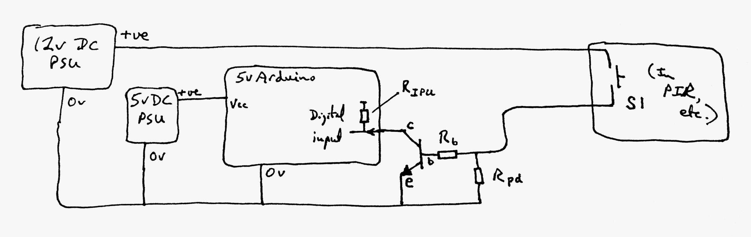
This is a circuit which will allow the connection... indirectly!... of a 12v signal into a microprocessor.
The particular application that sparks my interest today involves a PIR module, but the question is general in nature.
In the PIR, there is what boils down to a momentary SPST switch.
You could, as I said at the start, use an opto-isolator. But the above shows you how to use a transistor.
The resistor shown inside the Arduino, R-rpu, is the usual internal pull-up resistor which can be connected with....
pinMode(x,INPUT);
digitalWrite(x,HIGH);
R-b is a resistor to limit the current flowing to the base of the transistor... what we said above applies just the same here.
R-pd is a resistor provided to pull the base of the transistor down when S1 is open. About 10k would be fine.
Don't worry. Again as before, the 12v won't "leak" into the Arduino.
A kind person at the Arduino forum, someone I know to be reliable, says he's used a similar circuit with his PIR switch ore than half a kilometer from the Arduino. He further suggests putting a capacitor across the resistor R-pd, to reduced false positive arising from signals induced in the wire between the switch and the transistor's base. It becomes more important the longer that wire is. The wire will act as an antenna.
So! There you have it. Helpful, I hope.
One last little bit of information for beginners: Transistors don't (in simple ways) obey Ohm's law. If, for instance, you ONLY doubled the 12v that we are controlling or sensing, the current through R-b wouldn't just double. But all of that is a story for another day. I hope you have what you need, for now, to turn 12v devices on and off, or to sense a 12v signal without frying your 5v (or 3v3) Arduino?
![]() Page has been tested for compliance with INDUSTRY (not MS-only) standards, using the free, publicly accessible validator at validator.w3.org. Mostly passes.
Page has been tested for compliance with INDUSTRY (not MS-only) standards, using the free, publicly accessible validator at validator.w3.org. Mostly passes.
AND passes...

....... P a g e . . . E n d s .....