Am I just dim? I have struggled with what I am presenting here for YEARS... and I still don't know if I have this right!.
It is very rare from me to publish something unless I am sure of my facts. I hope I always make my uncertainty clear.
But after my years of struggle and study, there is a fighting chance that there is at least a shred of truth in the following. Use the information with a large pinch of salt... but maybe it can help you.
The early parts of this may be a bit of a struggle. But, right at the end, there is a "big reveal" which I hope will be a suitable reward to you for your effort. AND be USEFUL to you!
- - - - - - - - - - - -
In the following, there are two very similar circuits. (If you don't see diagram, look down the page... the Adsense panel sometimes pushes the diagram down.)
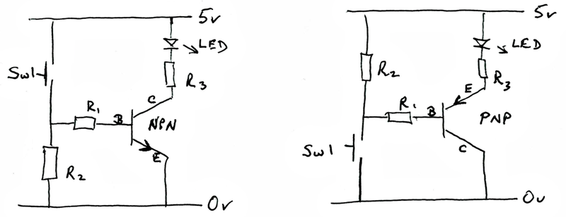
In both cases, when you close the switch (S1), the LED comes on.
"Compare and contrast": On the left, we have an NPN transistor. On the right, a PNP transistor.
On the left of each circuit, we have a resistor (R1) and the switch. But note... for the NPN circuit, the switch is at the top. For the PNP circuit, the switch is at the bottom.
So much for differences, apart from one more, which we can leave for a moment.
Similarities: In both circuits, R1 is a 1k resistor, R2 is a 10k resistor, and R3 is whatever limits the current through the LED to something reasonable.
In both circuits, one path taken by current, when it is flowing, is the path from the positive rail (the "5v"), through the LED, though R3, through the transistor, and "out" via ground ("0v"). Very little of that current will flow though R1, the resistor attached to the "leg" of the transistor marked "B", which stands for "Base", which is the name for that "leg".
Of course, some current flows through R1 and the transistor's base, in some circumstances.
That current is the "secret" of the whole story.
In an NPN transistor, current can flow from the positive rail, into the transistor, through the base, and "out" through the "lower leg" of the transistor, to ground. A small current will suffice. When a current flows like that, the LED will light, because the path for its current "opens".
In an NPN transistor, current won't flow out of the transistor via the base.
At this point, I must address an annoying source of possible confusion.
In both transistors, the leg connected to R1 is the "base" of the transistor. That's not the distraction; it's good news: at least one thing is simple.
The other two legs are the transistor's "collector" and "emitter"....
BUT!: Look closely at the diagrams. Notice: for the PNP transistor, the leg attached to ground is the collector. By a logic that might be the one that comes to your mind... as it did mine... you might think that this would still be the emitter, as it was for the NPN transistor.
After all, the LEDs current is "emitted" from the transistor along this leg. (Very little flows through the base leg, remember.) But that's just not the case.
Alas, the names "collector" and "emitter" are not about where the current for the LED comes from or goes to. (The names arise from electrons being collected and emitted in a different sense. You could probably try to learn all about that one day. (Wikipedia have a good article.) Happily, you don't have to learn that stuff for now.... as long as you remember that the "top" leg on an NPN transistor is the collector, even though the top leg on a PNP transistor is the emitter. Sigh.
Parts of all that work the other way around in the PNP transistor's circuit.
The "main current", the one that lights the LED, still flows from the positive rail to ground.
Now... read this next bit carefully... it is nearly what i said a moment ago...but it is "all turned around"!
In a PNP transistor, a small current will sometimes flow into the transistor, from the positive rail, through the emitter.. the "upper leg". This current will flow out of the transistor though the base, through R1, and down to ground. When a small current flows thus, the LED lights, because the path for its current (via the emitter and collector) "opens".
In the other transistor, the NPN, current won't flow out of the transistor via the base. In a PNP transistor, current won't flow into of the transistor via the base.
You should probably go back, read through all of that again at some point. It is "easy"... but also easily mixed up. But first, some odds and ends.
R2 is to force the voltage at the base to a known level when the switch is open. Very, very little current will flow... essentially none... when the switch is open, so there will be virtually no voltage drop across R2 (or R1) when the switch is open.
In the first circuit, the one for the NPN transistor, the voltage at the transistor's base will therefor be essentially zero volts. Thus, in the NPN circuit, R2 is a "pull down" resistor.
In the second circuit, when the switch is open, the voltage at the transistor's base will be essentially five volts. Thus, in the PNP circuit, R2 is a "pull up" resistor.
In passing: All of this would also work at other voltages, within reason. There's nothing "magic" about 5v. It would all certainly be the same at 3v3, for instance.
Why do we need R1? I don't know! But I believe with a degree of confidence that there "ought" to be one there. If not for the circuits discussed so far, but certainly for the one we are going on to.
Note that R2 is 10 times "bigger" (more resistive) than R1. This ensures that little current flows through R2 when the switch closes.
Were you wondering why all of this is about the transistor as a switch? (They can be"switches", of course... but weren't they originally mostly used as amplifiers?)
It's about the transistor as a switch, because that's where my interest lies! With different circuits, different transistors, yes, the transistor is an amplifier. Though the story is the same with a PNP transistor, if you swap the names around, taking the case of an NPN transistor: If you have a transistor doing amplifying, then you will be putting a variety of currents in via the base. And the current that flows from collector to emitter will vary as well... but it will be, say, 10 times the current flowing in the base.
What is "the right" transistor to use, if you want to use it as a switch? There are many. Look for "general purpose switching transistors". Some can handle large voltages. Some can handle large currents through the emitter/ collector path. I'm going to have to suggest you look for examples and copy the bits that seem relevant. There is more that I can help you with to deal with!
Are you pretty clear on the matters covered above? Have another read of the first section if you are not sure. It isn't "hard", but it is a bit... "tangled"?
So far, we "turned" the transistors... switches... on and off by pressing S1.
But the real fun begins when you use some digital device... say a Pi, an Arduino, or something else in place of the switch.
My "poor man's definition" of a digital output is that it is something that behaves a bit as though, inside the device, there were a switch. And the device can use that to connect the output either to the positive rail or to ground. I hope you see that's what I was trying to show at the left side of the following?
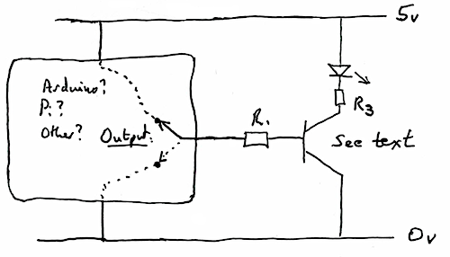
Notice that we no longer have the pull up or pull down resistor. We often won't need them... although sometimes you will need one. (Not all digital output connect you "very well" to one or the other rails. If there's a "good connection" to the ground rail, the output is said to be capable of "sinking" current. If there's a good connection to the positive rail, the output is said to be good at "sourcing" current. The size of the current that a particular output can sink or source is indicated in the device's datasheet.
Note: Just as with the names "emitter" and "collector" not meaning what you might have thought they would mean, note that an "output" sometimes has current flowing into. it. ARGH! Sad, but true. You'll get used to it.
You may think that I accidentally failed to complete the second diagram. (Actually, I did forget one thing... I could have labeled the base of the transistor.)
But it was not accident that I left the arrow off of the "transistor". Should I say "transistor skeleton? And it was no accident that I didn't label the other legs emitter and collector.
You see, you can put an NPN transistor or a PNP transistor in the second circuit.
If you make the circuit with an NPN transistor, the LED will light when the output from the Arduino or whatever is high.
Alternatively, if you make the circuit with a PNP transistor, the LED will light when the output from the Arduino or whatever is low.
Now... if you are using an Arduino, and reprogramming it isn't an issue, you could, say, always use an NPN in the switching circuit, and make sure that the Arduino's program makes the output high for when you want the LED on.
But you aren't always using an Arduino.
(Idle chit chat): the eureka moment that finally came for me, the moment when I "figured out" most of the above, arose when I was trying to use an NPN transistor to "connect" a standard PIR motion detector with an IP camera. Making the emitter/collector path conduct would make the camera take a picture. The trouble was, I wanted the camera to take a picture when the output of the PIR was low, not when it was high. Until I finally realized that a PNP transistor would be the answer for me in such cases, I was stuck. (Chit chat ends).
- - - - - - - - - - - -
A little bonus: Maybe you knew this already, but in closing I will just mention something you may find useful:
You can connect an LED directly to one of the pins of, say, an Arduino. LEDs operate on relatively little current.
You cannot connect, say, an electromagnet to a pin of an Arduino. Or anything else that will need much current to operate properly. (You can damage your Arduino, Raspberry Pi, etc if you try it!)
But the right transistor can handle a much larger current. And the transistor, as we have seen, can be turned on and off with the output from a microprocessor. So now we have a way to turn current-hungry things on and off, don't we!
(By the way... if the "current hungry thing" is a relay, you'll need the snubber diode!)
![]() Page has been tested for compliance with INDUSTRY (not MS-only) standards, using the free, publicly accessible validator at validator.w3.org. Mostly passes.
Page has been tested for compliance with INDUSTRY (not MS-only) standards, using the free, publicly accessible validator at validator.w3.org. Mostly passes.
AND passes...

....... P a g e . . . E n d s .....