 Bookmark this on Delicious
 Recommend to StumbleUpon
This page introduces hobbyists, etc, to some light sensors, in particular their characteristics, and uses with microprocessors, e.g. the Arduino.
The "right" light sensor for your needs depends on many things. The more you know about the sensors available, the better you will be able to choose the right one for your needs.
The page concentrates on three ways to sense light. Each can discriminate levels, but you can use them merely to distinguish "day" and "night", if that's all you need. In one discussion, the sensor is a specific make and model of light sensor. The other discussions cover two important classes of light sensor.
There's a footnote about sensors for infra-red (IR sensors), which are commonly employed in remote controls.
These would probably work fine on a NoviceGuard daughter board, NG_PwrDemand_1 or _2. Start by learning how to attach a potentiometer to a NoviceGuard. Once you understand that, I hope that attaching any of the following will seem trivial to you.
As you read these notes, keep your wants in mind. Do you want, for instance, for your current project simply want to know whether it is "day" or "night", or do you need to know levels? You will have a lot more fun with electronics when you approach things as a designer, rather than as someone who merely assembles other people's "recipes". A designer must think about objectives, and about balancing requirements and the properties of the alternative components available for the design.
The first two are essentially "resistors" which change their resistance according to the amount of light falling on them. (That characterization of a phototransistor/photodiode as a "resistor" will rightly annoy some (knowledgeable) readers.. but bear with me for a moment?
The Ambi Light Sensor is a three pin device, not expensive. (Only about $5, plus p&p, August 2011)
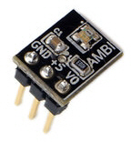
One pin for power, one pin to go to ground, and the final pin is an output, delivering voltage proportional to the light falling on the sensor. the voltage swings from near zero in near total darkness to nearly the voltage of the supply outdoors in bright sunlight. This is a tremendous advantage to the user. Also, the response is not linear. If it were, the "steps" at one end of the scale, as perceived by humans, would be too small, and at the other end of the scale the steps would be too large. It responds to light more or less as the human eye does, too, as far as frequencies are concerned. (Not all of the other sensors do. Some "see" infra red light quite well, for instance.). The Ambi Light Sensor is a great bargain for many situations where you care about the light levels, or where you are going to operating in variable conditions. But there will be times when even $5 is too much, or when you don't need all of the strengths of the Ambi Light sensor. For those times, I give you....
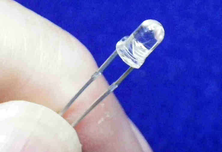
The LDR and the phototransistor/ photodiode are both two pin devices. (From now on, when I say "phototransistor", assume I mean "phototransistor or photodiode". I'm not going to address the difference between these two cousins in this page.)
The LDR is not polarized, it can be inserted either way around.
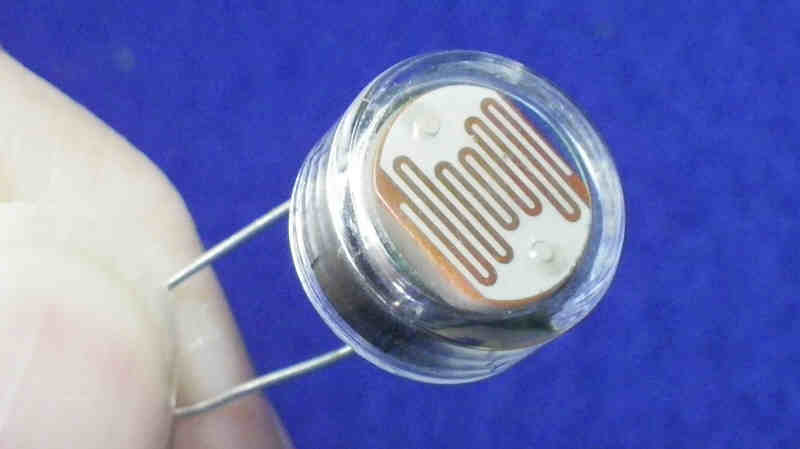
Something I read made me suspect that a LDR only "sees" a relatively narrow band of colors.... yellows and oranges. Unimportant in many cases, important in others.
(The phototransistor is a polarized device, and I don't think you can get away with putting it in backwards.)
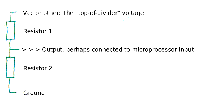
To feed an analog input, you would use either of the "resistive" sensors as one of the resistors in a voltage divider. (if the following circuit isn't obvious to you, you might want to take a detour to my discussion of voltage dividers. That link will open in a new tab or window, so it will be easy to return to this when you are ready.)
Let's say you put the light sensor into the following circuit, as "Resistor 1"...
That leaves us with working out how big Resistor 2 should be... what "ohms" or "k" (kilo ohms) should it have?
If we are connecting the output of the divider to a microprocessor input, analog or digital, we can assume that virtually no current will flow down that path.
Next we ask ourselves "What is the minimum resistance the sensor could present?" It may be a significant amount, or we may prefer to do a conservative design and assume that at some time the sensor will be exposed to conditions which make its resistance virtually nil.
The total resistance presented by the sensor and Resistor2 must be high enough to keep the amount of current flowing from the Vcc or top- of- divider voltage low enough. If it is too high....
If my Vcc was 5v, I wouldn't be too nervous about having a few voltage dividers in my circuit in which any one of them might present only 500 ohms when you add up the resistance of both Resistor1 and Resistor2. If you can make the resistance higher, good.
So much for what's the lowest Resistor2 can be. Why wouldn't you make it as high as possible, say 100,000 ohms? ("100k"). With some sensors that might be possible. A high resistance is good because less current will flow in this part of the circuit. Make it too low, and you will have problems. (Noise, and the amount of current flowing into the microprocessor input becomes high enough, relative to the other current, that you can't dismiss it.)
Another problem will probably arise before the current gets low enough to create the problems just mentioned.
The resistive sensors, in a simple voltage divider circuit, will always suffer in comparison to the Ambi Light Sensor on the criterion of range... but their performance may still be adequate! (And when it is not, you will have to learn about op-amps!)
Here's the thing:
I have an LDR which has a resistance of about 8 million ohms (8 megohms) in the pitch dark, and 70 ohms in bright sun.
Let's assume that you have a 5v Vcc, and have used a 500 ohm resistor for the other half of the voltage divider. With the LDR in the place of Resistor 2, once the light falls just a little bit, to give a resistance of 500 ohms... which is just a tiny part of the journey to 8 megohms... the voltage "seen" by the input will already have fallen to 2.5 volts by the rules of how voltage dividers work. (I've done a general essay on voltage dividers for you, too.). When the resistance of the LDR has reached 1000 ohms (1 k-ohm, or "k"), the voltage is going to be 3.3v.. a good portion of the "distance" to 5 volts, the approximate reading in the dark, will have been "used up" with just a relatively small change in light level. (Mine happens to be a "NORPS12", which cost me about $2, from a hobbyist supplier.)
Now this is not to say that the LDR is useless... far from it. But you need to be aware of the limitations. By careful choice of the fixed resistor in the voltage divider, you can get an adequate range of values across the range of light levels that interest you.
There's another thing about LDRs: They respond a little sluggishly. When I put one in the dark, here's what I saw after a little while...
Resistance in megohms: 8   10   12   15
Time since I started
measuring in seconds:  0   12   20   40
Not a "deal breaker" in most applications, but you might want to be aware of the sluggishness.
As I said, these are polarized. Put them in the circuit the right way around.
Much of what I said about LDRs is true, in simple terms, of phototransistors. However, they are much less sluggish in their response. Also, they are particularly sensitive to red and infra-red light, although other frequencies in the range visible to humans also affect them.
Strictly speaking, it isn't the "resistance" of a phototransistor which changes. They are "non-ohmic" devices... they haven't read Mr. Ohms' excellent (if short) book.
Strictly speaking, within certain limits, they will allow a certain current to flow at certain light levels. More light, more current.
However, if the voltage at the top of the divider remains constant, which it should, and if the resistance of the fixed resistor remains constant, which it should, then the phototransistor will "look" like something that changes its resistance as the light levels change.
Just don't try to extrapolate from data collected in one circuit to what will happen in another. E.g....
Suppose in your first circuit you had Vcc of 5v and Resistor 1 is 500 ohms, and you were seeing 2.5 volts at the divider output for a certain level of illumination. The phototransistor is behaving like a second 500 ohm resistor.
Now further suppose that you change the fixed resistor to 250 ohms. If the phototransistor was ohmic, the output voltage would rise to 3.3v... but this won't happen.
In the first circuit, the current must have been 5 milliamps, 5ma. (There was a 2.5 v drop across a 500 ohm resistor.)
If the phototransistor was ohmic, in the second circuit, the total resistance would have been 750 ohms, a current of 6.6 mA would result, and the voltage drop would have been shared out between the resistor and the phototransistor, 250:500, making the output voltage 3.3v.
But, as I said, that's not how it would work.
The phototransistor, in those light conditions will still pass 5 mA. The voltage drop across Resistor 1 will therefor be 1.25 v, making the voltage (compared to ground) at the output 3.75 volts... not far from 3.3 v, but enough to show us that the "simple" answer is, as usual, wrong. Sigh. But don't worry about it! You can still use phototransistors to sense light levels!
Here's how I should have connected the phototransistor in my ArduServer. (I inadvertently swapped the phototransistor and the resistor... but then compensated in the software. The principle of the voltage being divided remains the same.) Getting the phototransistor and the fixed resistor the "right" way around means that the voltage where they join, the "output" voltage, rises as the brightness of the light increases. With the components the "wrong" way around, the voltage decrease as the light increased. The diagram above is how I have got the components in my ArduSimpSrv, a similar device which set up a non-HTML client/ server system.) (If you visited the page before 1am (UK time) on 08 Oct 2011, you saw the two components drawn the other way. Reality/ components/ text now all in agreement... I hope! It will work either way! You may just have an "odd" scale!)
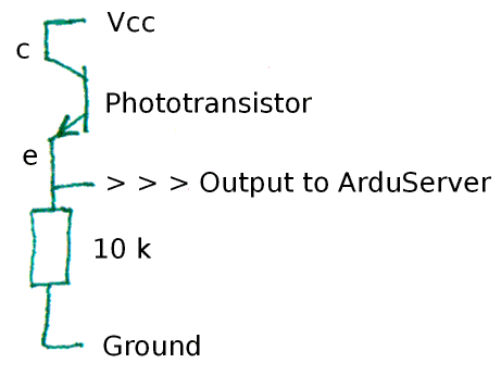
The "c" and "e" in the diagram indicate the phototransistor's collector and emitter.
I used a "NP64" phototransistor... or so I thought, based on the clear label saying "NP64" on the bag in front of me, from Maplin (UK parts supplier). However, at this point, I can, after half an hour of searching, find no evidence that an "NP64 phototransistor" ever existed, even at Maplin. It looks like a typical discrete LED with two radial leads. Digikey gives me 665 phototransistors to chose between... and that's when you leave out some of the similar devices offered for consideration after a "phototransistor" search! Digging around there turned up a number of things that were, I think, the general sort of phototransistor I used in the ArduServer... and the prices are good, typically about 70 cents. But I can't swear to you which way around the device should be inserted! Make sure you can get a data sheet for the phototransistor you select, and make sure you can tell which way to insert it! All of the phototransistors I turned up at Digikey were NPN types. A datasheet for one of them said that the collector was on the side of the package with the "flat", which was also the short leg.
Ha! I may not be clever, but I am STUBBORN. It seems that my phototransistor, the "NP64" is probably aka the Siemens (or Osram) SFH300-3, for which there IS a datasheet! And it also has its collector on the short leg by the flat! Digikey sells the SFH300 for 25 cents... if you buy a thousand. Sorry. Enough rambling. I'm sure you can find a phototransistor to know and love... they aren't rare beasts, it seems. RS components, in the UK, sells them for about 50 cents each in bags of ten. got there in the end! I hope the saga has given you a chuckle... but maybe I should edit the ramblings out? In the US, 8/11, Jameco sells the Vishay TEPT5600 for 45 cents, and it appears to be the sort of non-IR phototransistor I've been speaking about. (SFH300 does appear on the bag's label... along with the other four cryptic labels. After an hour's work, I came to the conclusion that NP64 was Maplin's stock code for something they discontinued.)
A few things to be wary of in your hunt for "your" phototransistor:
Some are engineered to be responsive primarily to infra red (IR) light. Fine if you are building a remote control receiver, not so good if you want to know how bright the day's light is. (One of the AmbiLight Sensor's virtues is that it is "tuned" to human responsivity.) Some have internal electronics to produce a digital output... switching from on to off at a specific light level. Fine for some things, not others.
There are just a few odds and ends left.
If you want to read more, there's a nice tutorial at Electronics-Tutorials.ws, where I was reminded that you could, if you'd a mind to, use a solar panel as a sort of light detector. But it has some more useful stuff, too.
People have used LEDs as light detectors. And you can. You can also drive screws into wood with a hammer.
Lastly a word about using beams of infra-red light to carry messages... as we all do when we use almost any line of sight remote control.
First of all, if you want to know if the sender is working, use a webcam to look at what you see if you "look down the barrel" of "the gun" while pressing a button on the remote. Many webcams are sensitive to IR light.
The people who make remote controls have come up with a neat idea to make them resistant to IR signals in the general environment. You don't want your TV switching channels just because a hot radiator is in the TV's command receiver's line of sight. (The hot radiator gives off IR radiation). The circuits for remote controls are set up to send, and only respond to, "flickering" beams of IR light. The "flicker" is of a very high frequency, so much longer "on"s and "off"s of the "flickering" beam can be interpreted as data. There's more on this on my page about using a remote control receiver. If you are thinking of making a "event- of- interest breaks the light beam" type of detector, seriously consider using a "flickering" beam, and one of the inexpensive little modules which only responds when the beam is flickering.
Sorry that rambled in places. Too much, or some incidental amusement for you? Comments welcome, contact details below.
![]() Page tested for compliance with INDUSTRY (not MS-only) standards, using the free, publicly accessible validator at validator.w3.org
Page tested for compliance with INDUSTRY (not MS-only) standards, using the free, publicly accessible validator at validator.w3.org
....... P a g e . . . E n d s .....