This page introduces hobbyists, etc, to the idea of a voltage divider. It concentrates on how they can help you connect things to analog and digital inputs on microprocessors, e.g. the Arduino.
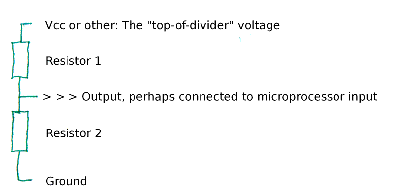
A voltage divider is not a component, it is a simple circuit...
Although sometimes you do things the other way up, and sometimes neither resistor's value is variable, for now we will assume that Resistor 1 is a sensor of some kind, and that its resistance changes in response to whatever the resistor senses.
We will also assume that Vcc is 5v.
Here's what happens with a circuit like the above....
The voltage is said to "drop" "across" each of the resistors. If, for instance, they were as big as each other, that is if they both gave the same resistance to the flow of current which the voltage is causing, then if you connected a voltmeter between the top of the diagram above, and the point marked "Output", then you would get a reading of 2.5 volts. We say "there is a 2.5 volt drop across Resistor 1".
If you then connected your voltmeter between the point marked "Output" and "Ground", you would again see 2.5v. There is a 2.5v drop across Resistor 2.
"Voltage" is never absolute. It is always measured between two points. If someone talks about "The voltage at such and such a point is...", they are implying that they have connected the voltmeter between the point they've specified and ground, ground being another name for the parts of the circuit directly connected by just wire to the "0 volts" pin of the power supply, or the "negative" end of the battery.
Just because we often measure voltages between ground and some other point doesn't mean that we will always do so.
Consider the same circuit as we had before, but this time, make the top resistor 100 ohms and the bottom one 400 ohms. In this case, the voltage drop across the top resistor will be 1 volt, and across the bottom one 4 volts. The voltage at "Output" will be 4 volts, when you measure between "Output" and ground.
The voltage drop between the top of the circuit and the bottom, between our Vcc and ground, will always be the same as the sum of the voltage drops across the resistors in the voltage divider. Keep the resistors 100 ohms and 400 ohms, but make Vcc 10 volts. Now the drop across the top resistor will be 2 volts, and the drop across the other 8 volts. 10=8+2.
Remember that we were once imagining that Resistor 1 was a sensor of some kind, and Resistor 2 a fixed resistor, and that Vcc was 5v? Suppose the sensor's resistance varies from 100 ohms to 400 ohms, and that the fixed resistor is a 400 ohm resistor.
In that case, what would the voltage at "Output" be when the sensor's resistance was high (400 ohms)?.... Don't scroll down until you've worked out an answer!
v v v v
... you do have an answer I trust? I said work one out!!/p>
v v v v
Did you get 2.5 volts? (You should have)
And when the sensor's resistance drops to 100 ohms? What would the voltage drop across it be then? And what would the voltage "at" the "Output" be then, i.e. what voltage would you see if you connected your voltmeter between "Output" and ground? Again... work out an answer before scrolling down.
v v v v
...4 v, right? Right!
So... a voltage divider sort of converts changing resistance into changing voltage... and it is voltage that determines what an analog input reads.
The simple, common way we connect a mechanical switch to a microprocessor's input... usually a digital input, but it would work on (if waste) an analog input is just a special case of the above... We replace "Resistor 1" with the switch. When it is closed, the resistance is zero, and all of the voltage drop occurs across the resistor, so "Output" "sees" 5v. Of course, the analysis of what is happening when the switch is open isn't quite as simple. It goes like this: For any voltage drop to occur, there must be some current flowing. With the switch open, there is no connection to Vcc, there is no reason for current to flow. "Output" is connected to ground by the resistor, and because there is very, very little current flowing, there is very very little voltage drop across the resistor, and "output" "sees" (very nearly) 0 volts. (In the circumstances given, a tiny bit of current flows out of the microprocessor's input. Without this tiny flow of current, the input wouldn't "know" what it was connected to.)
There's the little matter of current to consider, too. If the combined resistance of Resistor 1 and Resistor 2 is too low, excessive current will flow. Whatever the current is, the voltage drops across the two resistive elements will be the same as at any other current, for the same resistances... but if the current is too high Bad Things Happen.
At the other extreme, if the sum of the two resistances is too high, the current becomes very low. So low that it is near the level of the tiny amount of current flowing though the connection from "Output". This confuses the issue, and is also to be avoided.
That will, I hope serve you as a useful introduction to voltage dividers. If you keep the general principles in mind as you start working with specific instances of voltage dividers, I hope you will find you understand the instances more easily.
The principles are...
Voltage is measured between two points.
"Voltage drop" is the voltage across a part of a circuit.
The sum of the voltage drops across each of the two resistors in our simple series circuit will total the voltage drop across the two of them, the "voltage" of Vcc, which, pedantically, we might say ought to be described as "the voltage between the place marked Vcc and ground."
The ratio of the voltage drops will be the same as the ratio of the resistances. There will be a big drop if there is a big resistance.
You need to remember the current, too, which I'll come back to in a moment. First...
In a moment, we're going to look at how we might "adapt" a too high voltage to something lower, using a "voltage divider". Sadly, the "obvious" answer won't really work unless you are sure of some extra things. But before we turn to that: Beware: "Wall warts", the little black boxes which turn household electricity into lower voltages, don't always make DC voltage. Sometimes they make AC voltage. Look closely on the label of the wall wart to know what it produces. You knew that... but not everyone does! Back to less obvious matters...
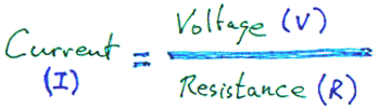
You've heard of ohm's law? It can be used here.
With a Vcc of 5v and two 400 ohm resistors, the current will be 5/400, 0.0625 amps, or 6.25 mA.
In a series circuit, which is what we have here, if the current is 6.25 mA in one place, it is 6.25 mA elsewhere.
What happens if you take 6.25 amps, the current, and 400 ohms, the resistance of one of the resistors? Put those together in....
.. and you can calculate a voltage (drop) of 2.5 volts!
Now consider Vcc= 5, Resistor 1= 100, Resistor 2= 400
Total resistance: 500 ohms.
Current through the two resistors, current to make a 5 volt drop with 500 ohms: 0.01 amps, 10 mA.
Now that you know the current, 10 mA... more, because the total resistance is less... you can work out the voltage drops. From the "ratios" and "total must equal sum of parts" rules, we already know that the drops are 1 volt and 4 volts. Isn't it neat that 0.01 times 100 and 0.01 times 400 also give us 1 volt and 4 volts?
Sometimes you will have the pieces of the puzzle to do the sums one way, sometimes you will have to make the journey by the other route.
And sometimes, you won't need the exact numbers, anyway. You'll be all set with just the broad ideas of a voltage divider's operation!
In the discussion above, we were talking about a circuit in which whatever the output went to was, it allowed very little current flow.
We're now going to look at a voltage divider when significant current does flow out that path, and we will see that it makes a difference.
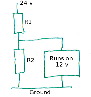
This is important, because it is a common mistake by beginners to think that what I've said above means they can, for instance, just use a simple voltage divider to "cut down" the output from a 24 volt transformer to "make it work" as a supply for something that wants only 12 volts. We'll use the wish to do that as the basis for an example.
Here's what the beginner wanted, what beginner hoped might work. The beginner used 1000 ohm resistors for both R1 and R2, and, by the logic in everything above here, the voltage going to the device that runs on 12 volts "should" have been half of the 24 volts, the 12 volts the beginner wanted...
But.
In all of the earlier discussions, an underlying premise was that very little current would flow away from the voltage divider from the point between R1 and R2.
The device the beginner wants to be provided with 12 volts does not present a high resistance to the current which is trying to flow. Let's say that it has a resistance of 1000 ohms, too... just like R1 and R2. What's going to happen?
This is another place where you should have a little think about how you would answer that question.
---
Got your answer? Don't scroll down until you do!
Okay... here's a diagram with red arrows to indicate the current flowing though the circuit...
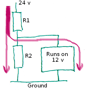
One thing to understand straight away: The red line is thicker before it divides than it is afterwards. This reflects the physics of the situation. The current flowing through R1 will be exactly the sum of the currents through R2 and the thing that runs on 12 volts, which I will be calling "the load" from now on.
Important: The arrows might suggest that the current splits 50:50. This will be true if the resistance each path presents is the same, not true otherwise... but I am not going to draw separate diagrams for every scenario!! You just have to remember that sometimes the left lower arrow is thick, sometimes the right lower arrow is thick.
What we learned above about voltage drops applies to the new situation... you just need a new rule. When you have two resistances in parallel....
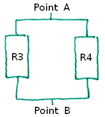
... the effective resistance, the resistance you would measure if you put your probes on "point A" and "point B", would be...
(R3 x R4) / (R3 + R4)
... a little tedious to calculate, perhaps, but simple enough in concept.
A moment ago, in our earlier circuit, we were saying that suppose R2 were 1000 ohms, and that the load were 1000 ohms. The equivalent resistance would be...
(1000 x 1000) / (1000 + 1000)
.. which is...
(1000000) / (2000)
.. which is...
500 ohms
Always ask: Does that seem reasonable? Well, with only one path for the electricity, the resistance would be 1000 ohms. We're supposing two paths, each of 1000 ohms. Yes... 500 ohms as the equivalent seems reasonable. And is in fact correct.
Lost yet? Take a deep breath. Review. We were wondering how....
... would behave, supposing, for the moment, that R1, R2, and the "Runs on 12 v" load had a resistance of 1000 ohms.
So far, we've determined that R2 + the load is equivalent to a 500 ohm resistor. That enables us to say that the equivalent of the whole circuit is a 1500 ohm resistor.
Now we're going to apply Ohm's law
The current flowing through R1 must be 24v / 1500ohms, which is 0.016 amps, aka 16 mA.
Now we can calculate the voltage drop across R1...
0.016 amps x 1000 ohms= 16 volts
... which means that the voltage "above" the load is only 8 volts, not the 12 the beginner who thought this would work had hoped. Oh shucks.
We didn't actually need to do all of the recent arithmetic.
As soon as we knew that R1 was 1000 ohms, and that the rest boiled down to 500, we should have noticed that in essence we had a simple voltage divider, and that 2/3 of the voltage would "disappear" (or "drop") crossing R1, and that 1/3 would drop across the R2/ load part of the circuit. (And 1/3 of 24 is 8, isn't it?!)
The beginner's wishful thinking won't work because the extra path for current represented by the load increases the current through R1. It also makes the "lower half" of the voltage divider have less (equivalent, overall) resistance... and both of those things mean that the voltage present "above" the load will be less than it would be if the load passed no current.
And worse: If the resistance of the load isn't constant, the voltage "above" it will keep changing, even if everything else remains the same.
While the last few paragraphs might have been enough to convince you that the beginner's idea wouldn't work, I hope you have struggled sufficiently to figure out the calculated "proof", too. That will give you tools for solving other problems, and for checking what "seems right".
Voltage is perhaps the hardest to understand of the three essential parameters...
... and, ironically, most novices think they understand it the best.
Resistance is fairly simple: It is the property of objects which opposes the flow of electricity. It is measured between two points.
Current is how much electricity is flowing. It is measured at a point.
Voltage is the force behind the electricity, but don't underestimate the subtlety of that. It is measured between two points, as we discussed... and not always between ground and some other point in the circuit.
The voltages you can measure between various places in a circuit isn't fixed like resistance. It "re-balances" as resistances in the circuit change. As resistances change, the current at different points change. Voltages change, too, but most people find fully understanding that more elusive than understanding the behavior of the other two.
But keep reading and experimenting, and your feel for how it works will grow!
![]() Page tested for compliance with INDUSTRY (not MS-only) standards, using the free, publicly accessible validator at validator.w3.org
Page tested for compliance with INDUSTRY (not MS-only) standards, using the free, publicly accessible validator at validator.w3.org
....... P a g e . . . E n d s .....