This page was written at the end of 2014. Since then, the product described here has been refined and extended. It now supports many USB devices, for a start! A new page for the Hobbytronics USB Host Controller was written in August 2020, and I would recommend you to read that... at least first!
Do you like the quiet life? Things to be simple? I do!
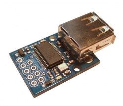
Hobbytronics, in the UK, sell a small board which makes it really easy to use a USB keyboard with a microprocessor. You only need a simple single digital pin set up to read serial data. The Hobbytronics site will tell you all the Good Stuff about the board.
(5v Arduinos and Teensys "do" "TTL serial data" with VERY little fuss or bother. Those of you in the 3v3 world are also welcome at the party... details at the bottom.)
The board "just works". This page is mostly to answer "Can it really be that simple?", and to say again some of the things at he Hobbytronics page, in case a beginner needs reassurance. If you are left with questions, please do get in touch, because I can easily revise the page, and the next person with your questions won't need to ask. If you are wondering, someone else will eventually wonder the same thing.
===
First catch your circuit. £14, (inc. VAT, but not the modest and reasonable p&p), December 2014. When ordering, be sure to use the pull down to specify that you want their general purpose USB interface module programmed to be a keyboard reader. (And while you are there, look a the other fun "toys" you can buy in further instances of the same hardware!)
Solder three wires to it. Any color will do, of course, but I would recommend...
Don't plug any of that in until the Arduino (or other) that you are connecting it to has been programmed, but I wanted to get how simple the hardware side is out there before turning to the not- much- more difficult software issues.
Just to See That It Works, we are going to connect a USB keyboard to the Hobbytronics module, and connect the module over a serial line to our microprocessor. In the demo below, I am using an Arduino, with pre- ver 1.0 software. That lets me set up a serial channel, using one of the general purpose digital input/output pins, and it also provides a useful tool (probably most often used for de-bugging) called the "serial monitor", which will display text in a window on a connected PC.
Once we've set everything up, when you press a key on the keyboard, the corresponding character appears in the serial monitor's display.
For that, the software is almost merely what you see below. Almost all of the "stuff" that is a bit obscure is just to set up the serial port that the Arduino will use to "see" the data being sent from the module. It isn't as bad as it looks.
void setup()
{
  #define SerialFrmKeybrd 2

  #include <NewSoftSerial.h>
  /*Not needed if you have Arduino 1.0 or later.
    As of 1.0, NewSoftSerial is included in the Arduino core, named SoftwareSerial.*/

  NewSoftSerial HtronicsKbd(SerialFrmKeybrd,SerialFrmKeybrd+1);
  mySerial.begin(9600);
  /*Set baud rate of the software to that used by
         the interface module*/
}// end of setup()

void loop()
{
int bIncomingByte;//create a local variable

//The "then" part of the following will only execute
//  after you have sent something to the Arduino
if (HtronicsKbd.available() > 0)//See if there's something
           //waiting in the serial input buffer. If there is...
    {
		// read the incoming byte:
		bIncomingByte = HtronicsKbd.read();
		// say what you got:
		Serial.write(bIncomingByte);//Send it to the serial monitor
     }// end of if's "then" block
}//end of loop()
The code below includes the details of "basic" use of the module. (I will cover the "advanced" topics later.)
Whether you are using an Arduino, or Teensy, or other microprocessor, don't worry about "the other half" of any serial port you may have available. In simple use, the UsbKbdToSerial board only needs your microprocessor to have a single line, a serial input (to the microprocessor) to feed the output of the UsbKbdToSerial board.
With an Arduino using pre-ver 1.0 development software, I suggest you use NewSoftSerial, and set up a dedicated port for the UsbKbdToSerial board. (I don't like using the "basic" serial port, especially in cases like this, where I also want to use the serial monitor. The two uses might clash.) (The Arduino, from ver 1.0 of the development software, incorporates what was in NewSoftSerial as its standard (Megas, I gather, have multiple serial ports available as "standard" SoftwareSerial.)
For the general issues, see my introduction to serial comms. From there, there is a link (cited once already, above) to the details of using the Arduino's serial monitor. That's couched in general terms. For displaying stuff from our test program for reading the UsbKbdToSerial board just read "UsbKbdToSerial" for "PC", and don't worry about the voltage level shifting issues if you are using a 5v Arduino. (That page also give you a way to drive the Arduino from a PC, and there's almost certainly a Lazarus alternative to the Delphi answer given. You could just use something like PuTTY. You need to deal with the voltage levels issues, if sending from a PC to the SerialVGA board.)
With a Teensy 3.0 or 3.1, here's the deal....
One way to drive the UsbKbdToSerial board is as follows....
It may be that the Teensy already has a second serial port up and ready. ("Second"? In other words, beyond the "basic" one on IO lines 0 and 1, used for programming and the serial monitor. I'm new to Teensy at the time I write this.) Failing that, download AltNewSerial.zip from....
https://www.pjrc.com/teensy/td_libs_AltSoftSerial.html
(I know... I hate add-ons, too... but this is probably worth it.)
I don't know the PROPER way to it add to your Teensy setup. While writing this 26 Nov 14, I'm using a Teensy 3.1, Win7 and Arduino 1.0.6 and Teensyduino (Teensy Loader) 1.20.
Before the next step, I just created an AltNewSerial folder in my....
C:\Program Files (x86)\Arduino\libraries\
.... folder.
I then just opened up the .zip with the basic Windows Explorer, and dragged copies of...
AltSoftSerial.cpp
AltSoftSerial.h
... and the folder...
config
... from the .zip archive into the newly created...
C:\Program Files (x86)\Arduino\libraries\AltNewSerial
===
Right! Tedious "do it once" stuff done. And remember: That was for a Teensy.
Here's how to use SerialToVGA and AltNewSerial in a Teensy. Similar code (different pins) for Arduino, but, if using pre-ver1.0 development software, you have to tell the NewSoftSerial which pins to dedicate to the job. (Use this link to jump back to what I said about NewSoftSerial, and serial comms, in general.)(In a post ver 1.0 Arduino, you have to tell SoftwareSerial which pins to dedicate.)
With a Teensy 3.0 and 3.1, for the Easy Answer, just use pins 21 and 20 for transmitting from the Teensy/ receiving to it, respectively. ("Pin 21" being the one also known as A7.) (You won't be able to use PWM 22 while using AltNewSerial. (What? You want your cake AND to eat it??)
As I've written the Arduino version, below, the data should come in via IO pin 2, and you should use pin 3 for output only. (Or better: Just don't use it. It has been allocated for serial output, which you aren't using, but SOME pin has to be allocated for that when you set up a pin for serial input.)
Plug your UsbKbdToSerial into your microprocessor. The green LED on the UsbKbdToSerial, lower right, if you have the USB connector on the right, should come on. Connect an ordinary USB keyboard to your UsbKbdToSerial via the standard USB socket on the UsbKbdToSerial. The blue LED to the left of the green one came on in my use... when I used a suitable USB keyboard.
(Sidebar: "Suitable" USB keyboard....
Oh dear. I have to admit. With the first keyboard I tried, the blue LED didn't come on; the interface didn't work. Sigh. That keyboard was an IBM SK-8805. Unremarkable to my untutored eye. It DOES have a small USB hub built into it. Maybe that is what makes it fail to work with the UsbKbdToSerial. I would be surprised if many USB keyboards fail to work with it, but can make no promises. If you want to plug in just a simple USB numeric keypad, I have no reason to think THAT won't work, although I haven't tried one.
... end sidebar.)
Right! Back to The Good Stuff. We've got our hardware all set up. I hope you programmed the Arduino first, but if you didn't do it now.
===
Here's a little sketch which will show you if you have your UsbKbdToSerial set up properly. Non Arduino/ Teensy readers will need to know that the line...
Serial.write(bIncomingByte);
... sends the byte in bIncomingByte to one of the Arduino/ Teensy system's development tools, the serial monitor. If you don't have an equivalent in your environment, the SerialToVGA board, also from Hobbytronics.co.uk, and an old, spare, doesn't have to be hi-res VGA monitor is something to consider.
/*
/*Program name: HtronicsKbd
  Minimal test, Hobbytronics.co.uk's
    USB-keyboard-to-Serial-signal device.

 ver 13 Dec 14
 Started 13 Dec 14 after nice meal
     at Rustica

 Connections:

 Hobbytronics USB board's 5v and 0 to same on
 Arduino, i.e. Hobbytronics board powered from
 Arduino.

 Also the pin marked "TX" on Hobbytronics board
 is IT's output... and input TO the Arduino, an
 input FROM THE ARDUINO's point of view.
 That to be connected to the pin you want
 to use for the signal from the keyboard.

 I was using the pin for the Arduino's digital
 line "2". You can "re-program" this to use
 a different line just by changing what
 SerialFrmKeybrd is set to. I would avoid
 lines D0 and D1, because they are used in
 programming the Arduino, and in the built-
 in "Serial Monitor", which I am using in
 this program to see what is being sent
 from the keyboard attached through the
 Hiobbytronics device.

 Not that I am also "using" the pin after
 whatever pin I've designated for data to
 arrive over. This pin is set up for the
 Arduino to use to SEND some serial data...
 but the only sending we are going to do
 sending text to the built in serial monitor,
 and the sending will not be via the serial
 port (HtronicsKbd) set up with NewSoftSerial.*/

#define SerialFrmKeybrd 2
//"Sets" the system to use pin 2... or some other,
         // if you change the number.
//Do not put = in, or semicolon after the above.

#include <NewSoftSerial.h>
/*From Arduino website: Note: don't download this
  if you have Arduino 1.0 or later.  As of 1.0,
  NewSoftSerial is included in the Arduino core,
  named SoftwareSerial.*/

NewSoftSerial HtronicsKbd(SerialFrmKeybrd,SerialFrmKeybrd+1);

void setup()
{
Serial.begin(9600);//This to configure serial monitor
  Serial.println("Welcome to HtronicsKbd");//this sent to serial monitor
  Serial.println("Visit sheepdogsoftware.co.uk for further useful stuff.");
  delay(1200);// Give reader a chance to see the output.
}
void loop()
{
int bIncomingByte;//create a local variable

//The "then" part of the following will only execute
//  after you have sent something to the Arduino
if (HtronicsKbd.available() > 0) {
		// read the incoming byte:
		bIncomingByte = HtronicsKbd.read();
		// say what you got:
		Serial.write(bIncomingByte);
     }// end of if's "then" block
}//end of loop()
That little bit of code should cause....
First, the following should appear on the serial monitor (once you open it! If you are too slow, you may miss the text below)....
Welcome to HtronicsKbd
Visit sheepdogsoftware.co.uk for further useful stuff.
After that, press some keys on the keyboard. If you press an "a", you should see an "a" on the serial monitor. Hold down the shift key, press the "a" key again, and you should see "A" on the serial monitor.
So far, so good. We have a keyboard connected to an Arduino or other processor. And we can "see" keys as we press them... as long as we stick to simple things like a-z (shifted, or not shifted), the digits (0-9), basic punctuation marks.
The rest of this section gets a bit esoteric. As long as you only press letter or digit keys on the keyboard, you can ignore it. You can also look at the demo program on the Hobbytronics page and infer a lot about what is going on from reading the code there. But, for those who want to cross all the t's, here we go....
What about the "special" keys on the keyboard? The "enter" key, "up arrow", "down page", the function keys (F1, F2, F3...)?? And "ordinary (and other) keys, but pressed while holding down either the control key, the alt key, or both??
Most, if not all, of these things are taken care of by the UsbKbdToSerial interface board with "escape sequences"... a "sequence" of two numbers sent out on the serial output to "say", for instance, that the "delete" key was pressed.
"Escape sequences" are a long established way of dealing with the sort of thing they are used for here.
If you press the Delete key, the interface board first sends a "special" number, which has been put aside.
65 is an UN-special number: In computer displays, and on printers, it has been long agreed that where the number is 65, the character printed should be a capital (i.e. upper case) "A". ("Agreed" in the "ASCII code" tables.)
But zero and 27 are not assigned printable characters in the ASCII code. And thus one (usually 27) or the other can be used to say "Ignore me, and then do something different than you would ordinarily do with the next character you receive. The 27 (or zero) is called the "escape character", or "escape flag".
On a hasty reading of the Hobbytronics page about the UsbKbdToSerial device, I have a slight suspicion that a bit of inconsistency has crept in between the documentation and the board's operation. It is a trivial matter, if it even exists. (It is just that in some cases... at the time I write this... seems (on hasty reading) to be "confused": Sometimes saying that the escape character used is a zero, other times saying it is a 27. From actual experiments, 27 seems right in the few cases I tested.)
Ctrl-A has for a long time, in general, been meant to generate the number 1... not the ASCII code for the "one" character. (The number you get if you press the one key, the ASCII code, is 49 (that's what it is expressed in decimal. When you see a number written like this: "0x49", you are being given a number expressed in hexadecimal, aka "hex".). And the UsbKbdToSerial interface, sensibly, behaves just like that. Press Ctrl-A, and a zero is sent out on the serial line. The simple program above will be somewhat confused by that, and probably give you a square in the serial monitor to say "I had a code I don't know what to do with." It would seem that 32 CTRL+ something-else key presses have been assigned the numbers 0 to 31 as what the interface board will generate. Ctrl-a produces 1, ctrl-b produces 2, etc, up to ctrl-z produces 26 (that's 0x1A, in hex.) For the keys to get the few remaining codes, see any ASCII table, or the table provided by Hobbytronics, which goes into some more of the keys which give rise to escape sequences.
In practice, it really is not too terrible!
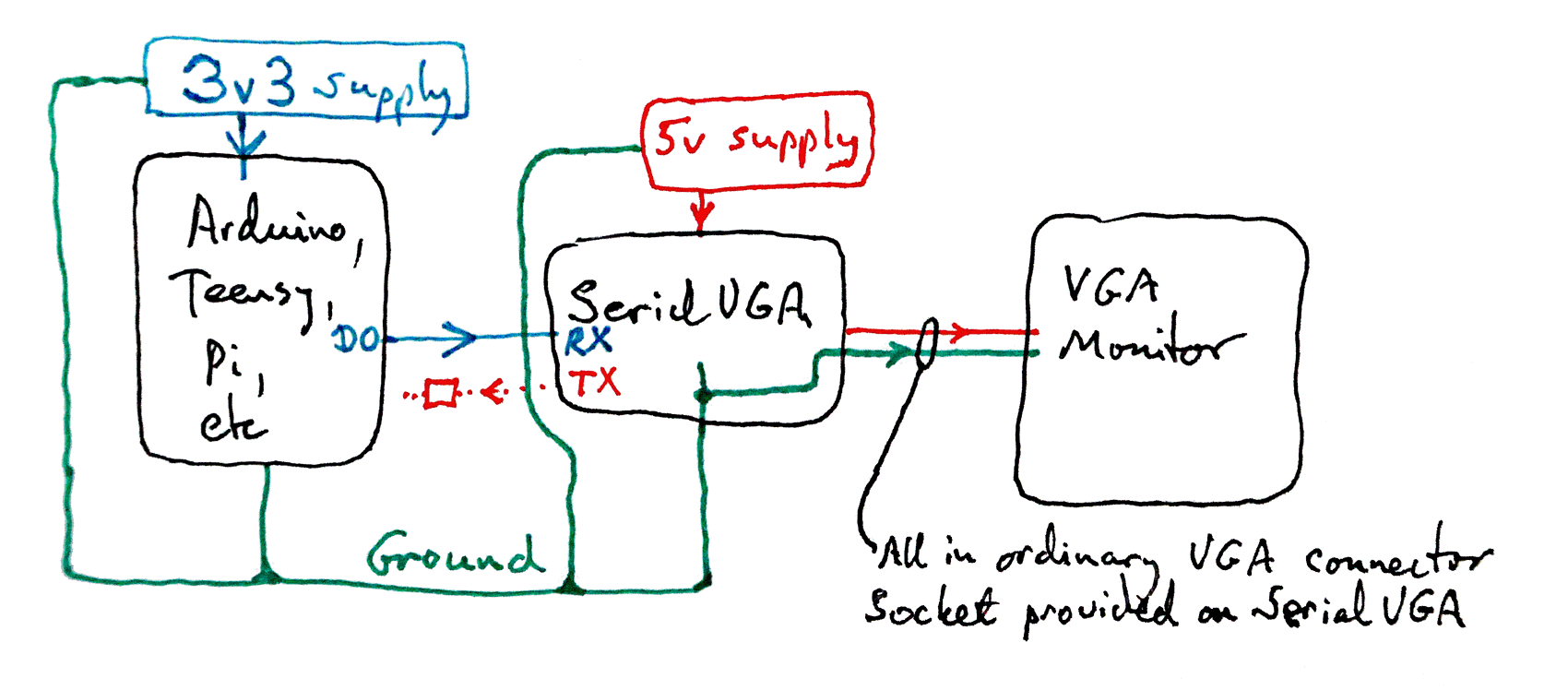
The following isn't exactly what we want here... but it has a lot in common with what we DO want! Your UsbKbdToSerial module will go in the place of the SerialVGA module in the center of the diagram. You will be connecting a USB keyboard where you see "VGA Monitor" in the diagram. And the connection is by "ordinary USB socket" on the UsbKbdToSerial module, of course.
You run your system on its usual 3v3 supply. Of course, your external supply may deliver a greater voltage, if you are using a system with onboard voltage regulation. Both your system and the supply must be connected, in the usual way, to the overall ground.
The UsbKbdToSerial module needs... I think!... a regulated 5 volts. (MAYBE that could also run on 3v3, but I know you CAN run it on a 5v supply. You do need one or the other"!) And the grounds need connecting, as the Arduino and Arduino supply were connected.
You will NOT be making the D0 to RX connection shown in the diagram in cyan.
Newbies: Be careful, but not too careful. Yes: The grounds need to be connected together, as shown. Don't worry that the 5v for the SerialVGA board (and the signal to the VGA monitor) will "leak" into your 3v3 electronics. Voltage just doesn't work that way. Nor will the whole thing work if, in particular, the connection between the ground coming out of the "bottom" of the SerialVGA (UsbKbdToSerial) module is not connected to the ground coming out of the bottom of the Arduino, Teensy, Pi, Whatever. (I.e. the bit of wire under the word "ground" in the diagram.)
The "connection" between the UsbKbdToSerial module and the USB keyboard doesn't require any effort from you. The module has a normal USB socket: You just plug the keyboard in, as you would plug it in, say, to a PC. (Power for the keyboard is drawn through the connection, as well as it being how data flows.)
The serial data you must send to the Arduino (or other) will come out of the UsbKbdToSerial board via the pad marked "TX". This is shown on the diagram in red.
I'm not sure exactly what you have to do "to" the signal if you are "feeding" it to a 3v3 Arduino. At most it involves a few resistors, but you are going to have to find advice on that point elsewhere. Perhaps it only needs a simple passive voltage divider. I am ** NOT ** saying you can "just connect it" to the pin you've set up for the serial input.
![]() Page has been tested for compliance with INDUSTRY (not MS-only) standards, using the free, publicly accessible validator at validator.w3.org. Mostly passes.
Page has been tested for compliance with INDUSTRY (not MS-only) standards, using the free, publicly accessible validator at validator.w3.org. Mostly passes.
AND passes...

....... P a g e . . . E n d s .....