I don't know a lot about servos. Would welcome comment from the "experts", but, that caveat aside....
If you are new to "servos", or even not sure that a servo is quite the electricity- to- movement gizmo your project needs, head over to my "overview" page at http://www.arunet.co.uk/tkboyd/ec/ec1motors1.htm. That will open in a new tab, making it easy to return here again later.
One thing I do know: Servos come in various "types". (And, of course, within them, in various strengths, reaction times, operating voltages, etc.)
What I am about to present is a way that I THINK would work to make a bunch of servos go to one of two positions, based almost entirely on closing one switch per servo. Much less complicated than all you would do to control multiple servos "the ordinary" way. My trick can even be extended to several positions. You give up the "infinite" variability available when using servos "normally".
(If you are interested in a more general page about electric/ electronic "motors", that will open in a new tab, making it easy to return here again later. It discusses alternatives "motors".
I also offer a page about the basics of working with servos.
As I said... I'm no expert when it comes to servos. But I think there is a type that works as I will explain, by reference to the following....

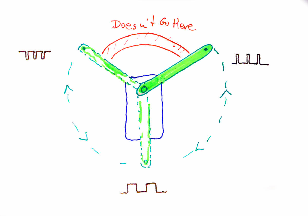
I think there is a type of servo (dark blue rectangle) with an arm (green) that swings though part of a full circle (dotted green lines), but no further, i.e. not into the red arc. I may use "clock" references from here. I drew the arm pointing up to the right solid to say "here is where it is just now", and I will call that position "2 o'clock".
The other two "arms" are drawn dotted to say "the arm might be here... or here." I certainly never saw a a servo with three independent arms! I would call the other two arms' positions 10 o'clock and 6 o'clock.
So much for naming of parts.
It is my believe that when there is no voltage applied to the servo's input, the arm swings freely.
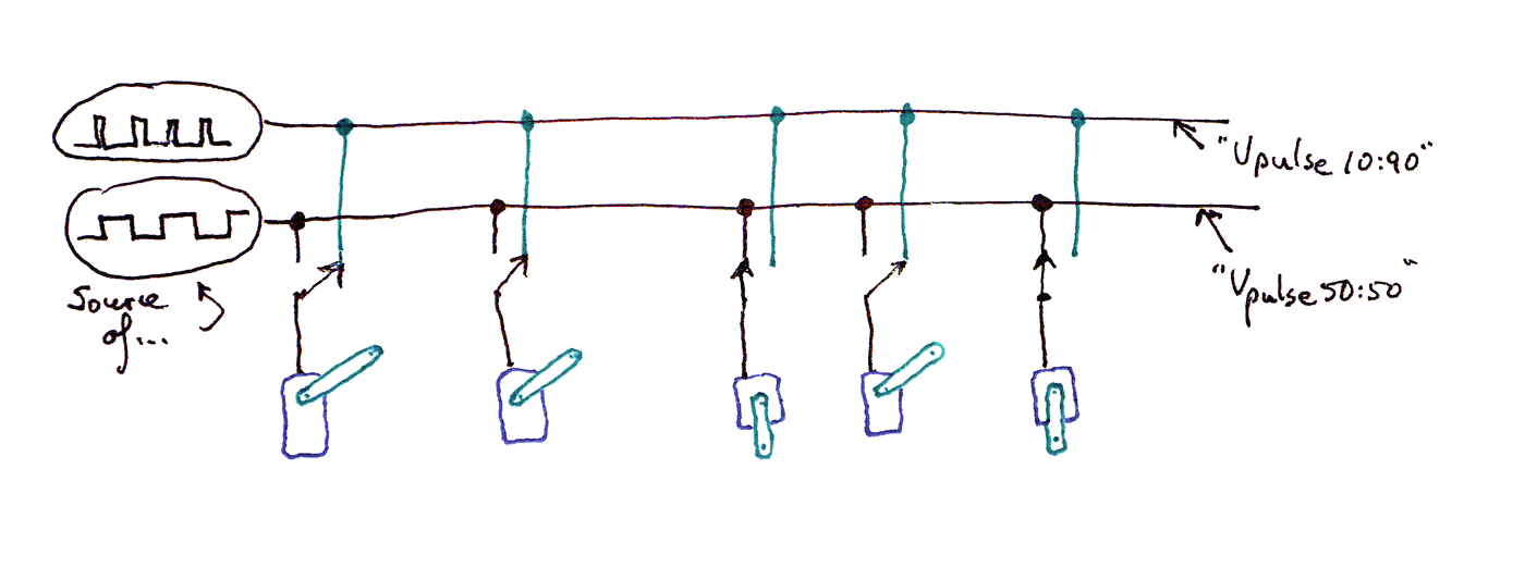
All is not lost if your servo does not swing freely when no pulse train is present. In fact there is a silver lining. You can implement something similar with SPDT switches, "common" terminal of switch to servo, and the two poles select between two different pulse train "feeds". (The switches need to be of the "break before make" type.) The silver lining is that you no longer need the springs. Of course, the "switches" may be electronic, rather than mechanical.
Apply a pulse train, and the arm moves to a pre-defined position... in the case of my hypothetical device, if the pulse train is a lot of long "highs", with brief "lows", the arm goes to 10 o'clock. (I've drawn the pulse train for each position next to the arm there.)
Apply a pulse train where the highs and lows are of roughly equal duration, and the arm goes to 6 o'clock. And long lows, brief highs would put the arm at 2 o'clock.
So far, so good? Remember: what I've told you so far may not be true!! (But "experts" who've looked haven't complained about too many flights of ignorance.) And even if true for some servos, will not be true for all servos.
If you are using a servo motor with an Arduino, there is a library ("Servo") to make your life easy. It deals with generating the stream of carefully timed pulses. Beware: Only some of the Arduino's outputs can be supplied with a stream of pulses. Which outputs are pulse- stream- capable varies from device to device. In other words, the I/O pins you can use for a servo on, say, a Uno, might be different from the pins you can use on, say, a Mega.
But! If what I said above is true, I think that the following, or electronic equivalents, would work for a need that arises from time to time.

Suppose you need the arms of multiple servos in one of two positions? (2 o'clock and 6 o'clock in the example above.)
Use a spring (in cyan, first one marked "Sp") to pull the arm around to the first required position. ("F" is a fixed post, against which the spring pulls.) (See note above for What You Can Do with the sort of servo that doesn't turn freely when not receiving signal.)
Arrange for ONE source of a pulse train of the required ratio of high and low. Shown in the diagram at the upper left. (Marked... "Source of..., and that "net" of the circuit marked, right hand end, Vpulse.)
"Feed" (connect) (or not) that pulse train to the various servos through a switch. (Left hand one marked "Sw".) Switch closed: servo's arm goes to position defined by high:low ratio, in this case, 6 o'clock. Switch open: servo's arm goes to defined-by-spring position, in this case, 10 o'clock.
Simples! Brilliant! (If it works!)
I've described this in words elsewhere on the page....

Obviously, the more complex switch is a pain if not using relays. But it does have the virtue of not needing the "pull it back to alternate position" springs, and of working with servos which don't turn freely when their inputs float. Regardless of whether the switches are mechanical or electronic, they need to be of the "break before make" type. You don't want to short Vpulse50:50 and Vpluse10:90, even briefly.
![]() Page has been tested for compliance with INDUSTRY (not MS-only) standards, using the free, publicly accessible validator at validator.w3.org. Mostly passes.
Page has been tested for compliance with INDUSTRY (not MS-only) standards, using the free, publicly accessible validator at validator.w3.org. Mostly passes.
....... P a g e . . . E n d s .....