This material is presented for people who have very little experience of the hardware side of computing. Go to my main parallel port projects page if you are not in this category.
Don't let the warning above worry you too much... I want to stress that there is a lot of fun to be had with electronics projects. Find yourself an 'antique' PC. If you can't rescue one from a dusty corner, you can buy one for almost nothing. You can use the same monitor as you use on your main machine. If you wreck the antique, it hasn't cost you much! (I got one, with monitor, off a sidewalk once!)
If the computer you work on is not yours, e.g. it was bought by a parent, or belongs to a school, please consult the owner before making any connections!
I have a third generation 'protect the PC' circuit in development, intended for schools. You interpose it between your PC and the home-made stuff you are attaching to the parallel port, and any mistakes in the home-made things are blocked off from the computer. I have posted a separate page about this parallel port protection circuit, which includes a way to download the circuit diagrams.
Having got those warnings out of the way...
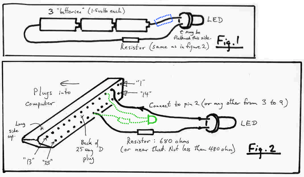
Two diagrams should appear below. If they don't, they are is online at www.arunet.co.uk/tkboyd/LEDFig.jpg (One graphic holds both of them.)
Connect an LED and a resistor to a battery of 3 cells, as shown in the black lines of figure 1. It doesn't matter which way 'round the LED is... if it isn't the right way it won't work... but no harm will be done. If it doesn't work, just reverse the connections to the battery... the resistor can be on either "side"; the blue rectangle is there to say "resistor could be on this side". I used a resistor of 680 ohms. If yours is too big, the LED won't glow. Too low isn't good either... I wouldn't go below 400 ohms. (That figure is for a "normal" red LED. If you have a different one, you can still try 680, but it may be a bit dim or bright.)
The cells in the battery can be whatever you have to hand... C, D, AA, AAA... it doesn't matter as long as they are 1.5 volts each. If you want to use something bigger, you can't simply double the resistance if the voltage is doubled. About 500 ohms should be okay for a 9v battery. If you haven't got that, start with something higher, and work downwards. (Go to the Electronics Club's excellent page on LEDs for more detail, if you wish.... it really is a little embarrassing that my page came higher than that in a Google search just now! The Electronics Club's page is very polished!... but maybe my page has its merits, too?)
Until you can get your LED working as in figure 1, there's no point in going on to figure 2... something's wrong, and you're better off figuring it out with figure 1's circuit.
Once the LED works as shown in figure 1, connect things as in figure 2. The wire to pin 2 of the connector is the one that went to the positive terminal of the battery, i.e. to the end with the little "button" to connect to.
Send zero and 255 to the printer port. (See my parallel port projects page for the software issues). The LED would be on in one case, off in the other... probably on for 255, but maybe not.
The dotted green lines are there to show you how to add additional LEDs. Each should have it's own resistor. Again, it can be on either side of the LED. Each has one leg attached to pin 19 of the connector, and the other goes to a pin from the range 2 to 9. Each of those pins (2-9) should "drive" (i.e. be connected to) just one LED.
Good luck! Enjoy! It is pleasing beyond all reason to watch a few LEDs wink away.
For more details, including how to calculate the right value for the current limiting resistor, see my page about designing with LEDs. I've also done a page about using LEDs aimed primarily at Arduino users which anyone using microprocessors might find useful.
If you are very new to digital electronics, It may pay you to visit my tutorial on the subject of inputs and outputs.
Click here to visit editor's freeware, shareware page.
Here is how you can contact this page's editor.
Click here to go up to general page about electronics by editor of this page.
Click here to go up to general page about electronic projects by editor of this page.
![]() Page tested for compliance with INDUSTRY (not MS-only) standards, using the free, publicly accessible validator at validator.w3.org
Page tested for compliance with INDUSTRY (not MS-only) standards, using the free, publicly accessible validator at validator.w3.org