 Bookmark this on Delicious
 Recommend to StumbleUpon
The following isn't too crude to follow, I hope?
It tries to show a relay (in green box), powered from a voltage source called "Vr". Current would flow from Vr, though the relay's coil (not, at this stage through the diode), down through the transistor, and finally to ground.
I said "would" flow.... it depends on the voltage coming from "Out", which is supposed to be a connection to the output of some other circuit. That could, for instance, be an output from an Arduino or other microprocessor.
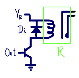
I'll try to get back to this, tell you more about choosing the transistor another time. For some small relays, you could just connect the "bottom" connector from the relay coil to the microprocessor output, and be done with the rest... IF "Vr" was being drawn from the Vcc of the processor, and if the relay was small enough that the current would be minimal.
It's like this....
There's no problem when current first begins to flow through the coil. There's no problem as long as it continues to flow through the coil.
However: When the relay is "turned off", when the path to ground is "disconnected", a very brief, but very nasty event occurs.
There is, while current flows, an "electro-magnetic field" (EMF) around the coil. When the current ceases to flow, that field "collapses" into the coil....
I've given that the dreadful typography in an attempt to get your attention. Without the diode, which we'll come to in a moment, it is as if you have connected some source of voltage to the output backwards. This is a Very Bad Idea.
Happily, all you need to do is connect a diode, as shown. It will short circuit the reverse EMF when it occurs. While the voltage is high, the charge behind it is not large, and the diode will "soak up" the brief attempt to damage your output.
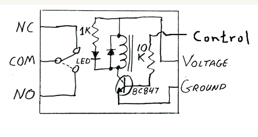
(Sidebar: Actually- you can save yourself all sorts of "stuff" if you just break down and BUY a relay module. Yourduino.com has a very nice one, for only $5 (+p&p, Nov 17) Also, YourDuino.com's wiki has many pages like this one... but done to a much higher standard! End sidebar.)
I won't promise that all of that is exactly, technically right... but I will promise you that putting the diode in is a good idea! Put the diode as close to the coil as you can without unreasonable struggles.
The coil in a simple DC motor will do the same thing. If you are going to reverse the direction of the current through the motor to make it "go" "forwards" and "backwards", you will need to put the diode just "upstream" of the place where you reverse the connections to the motor from time to time.
Stepper motors will also need care taken, but these are often driven by dedicated circuits, which will contain the necessary diodes... but be sure your's does! Include diodes if you are driving servo coils directly.
I hope this reached you before reverse EMFs damaged any of your microprocessors? Do please write in and tell me if bits were unclear, or you would like more help with optoisolators
There is no reason you couldn't connect a relay via a NoviceGuard daughter board. You would need to use the NG_PwrDemand_2 power scheme. If the relay coil were not the same as your Arduino's Vcc, you'd need a separate supply for the relay coil, but the transistor you would use to switch that power is shown above.
I have to confess that I have not tried it... yet.
![]() Page tested for compliance with INDUSTRY (not MS-only) standards, using the free, publicly accessible validator at validator.w3.org
Page tested for compliance with INDUSTRY (not MS-only) standards, using the free, publicly accessible validator at validator.w3.org
....... P a g e . . . E n d s .....