LCD displays have become so inexpensive and easy to use that we could be forgiven for neglecting the humbler seven segment LED display... but the LED displays do have some strengths...
There are solutions even less expensive than the one presented here... but how hard do you want to work to save $13? (It comes in many colors, by the way) Furthermore, other 7 segment LED solutions will "cost" you more pins from your controller, and extra lines of code in your software. The solution presented here only needs one pin. (Well, two, but you only use one of them. You probably could use the "unused- by- LED module" pin for some things, if you were careful. Details below.)
If you don't happen to be using an Arduino as the processor driving the 4 character LED display, fear not... much of the material here will still be useful to you if you have ANYTHING capable of generating serial data, e.g. a Pi. (But look into Arduinos! They are inexpensive and... dread word... "powerful". And very developer-friendly.)
Which serial port? Who knew there were so many choices? When this article first written, the one I liked to use... it worked for me, simple scenarios... was NewSoftSerial. Now I tend to use "SoftwareSerial". But there are other choices, if you want to explore them. (If you are not "happy" with libraries, stop avoiding them now... but still be careful about what you use. I explain libraries for Arduino users in another of my tutorials.)
The device this essay was inspired by has been retired. But new ones, fully backwards compatible with the old one, as far as I know, exist. They come in several colors. The current (12/18) blue serially driven 4 digit 7 segement display cost (12/18, exclu p &p) $14.
One of the reasons you see me talk about Sparkfun so often in my pages is that I find their stuff Just Works, and that they have great product information pages, supporting their customers. These 4 digit, 7 segment LED modules have, in general, Just Worked for me... but 12/18, I struggled a bit with an old one.
For simple "put digits on the display"... no problems. My struggles began when I tried to "get clever", and play with the colon. Something I know I did when I wrote the bulk of this essay, no problems.
Here are a few things that I came across, didn't fully resolve...
Is it...
Serial.print("v");//worked for me, in past Note: Must be v no V
Serial.print('v');//does the choice of " vs ' matter here?
Serial.print(0x76);//should work like v... didn't seem to
Moved bacon... bytes/ binary format...
mySerialPort.print(B00000011,BYTE);//Old Skul
  mySerialPort.print(0x00000011);//Compiles now... I think
     //it does what I hope it does, but this was
     //in the midst of other not fully resolved things.
If you are trying to send zero as a byte, you may STILL have a problem. To send zero, create a byte-type variable, put zero in it (byte bZero=0;), and print THAT...
Serial.print(bZero);
Remember: I still think these are great little devices. I did not have problems with putting digits on the display. (I was trying to use the display as a part of a bigger project.) My "problems" could well be to errors in my code.
I've created a subordinate page with a little more detail on the problems I did have. By all means skip it, unless you too are having trouble with making the colon, decimal point, etc behave. (Or other "advanced" use of the display.)
One of these modules would probably work fine on a NoviceGuard daughter board, NG_PwrDemand_2, although I have to confess that I have not tried it... yet. The module would give your NoviceGuard a four digit output, so perhaps worth some effort.
You can see the connections you need to make in the photo above, at the top edge of the module:
Not onerous!!
N.B.: That is just one of the TWO ways you can connect the module to an Arduino, or other host. You can also use the SPI, if you wish to, and can find someone else to explain any details you need help with! It takes more wires, more work. I'll use the provisions of NewSoftSerial, thank you... and commend the same to you.
The following code will put "1234" on the display module. And a moment later, what is displayed will change a few times, and then the whole thing will repeat endlessly.
//ArdD001
//ver 12 Aug 10
//(Started 12 Aug 10, 277RR, 2nd day there.)
//Created using version 0017 of the Arduino Development Environment
//Very, very simple "test" program for Sparkfun
//4 character 7 segment LED displays, serially driven
//using just the "Rx" input on the module.
//See Sparkfun.com... product codes COM-09764 - COM-09767
//(differ only in color)
//Connect one of the above modules to an Arduino with
//just 3 wires: 5v (Vcc) (or 3.3, if you are using a
//low voltage system. Module is good down to 2.6v)
//Also connect to "GND" (ground), and with a wire from
//the "Rx" pad of the module... the MODULE is receiving
//it's commands through this... to the pin you choose to
//TRANSMIT data out from the Arduino on.
//If you use D3, then nothing below needs a change.
//If you use a different pin, then change the....
//#define SerOutFrmArdu...
//line.
//When you run the program, you should see the following,
//one after the other...
//1234
//2340
//3400
//4000
//0000
//----
//8888
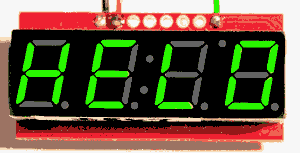
//HELO
//(That last is the best we can do for "Hello World" on
//a 4 character, 7 segment display)
//... then there will be a brief period when all the
//LEDs are off, and then the display will repeat the
//above. All that happens over and over.
//Simple! When you know how. I didn't, and it took a
//while to get everything right. I hope you come
//across this in time to save yourself the time I wasted.
//12/18: You might want to use SoftwareSerial
// instead of NewSoftSerial
#include <NewSoftSerial.h>
//Yes, NEWSoftSerial...
//I don't think SoftwareSerial has the
//"available()" function, does it? Not
//needed here, but might as well stick
//to one library for all work with
//extra serial lines.
#define SerInToArdu 2//no ; here. Not used in this demo,
// but in defining mySerialPort, we to designate some pin
// for the serial data into the Arduino
#define SerOutFrmArdu 3//no ; The pin that serial data
// will go out from the Arduino on. Beware "Rx"/"Tx"
// "gotcha": The Arduino's "Tx" (transmit) will go to
// the connected device's "Rx" (receive)
#define wDelay 600//no ; here. Sets how long each "message" appears
NewSoftSerial mySerialPort(SerInToArdu,SerOutFrmArdu);
// The above creates the serial channel we will use.
void setup(){
pinMode(SerOutFrmArdu,OUTPUT);
pinMode(SerInToArdu,INPUT);//Not actually needed... put in
//to be explicit as to data direction over serial lines
mySerialPort.begin(9600);
mySerialPort.print("v");To reset display module
//See next demo program for more details, and text
//in "Special Codes" section of....
//http://www.arunet.co.uk/tkboyd/ec/ec1led4x7ser.htm
};//end "setup()"
void loop(){
mySerialPort.print("1234");
delay(wDelay);
mySerialPort.print("2340");
delay(wDelay);
mySerialPort.print("3400");
delay(wDelay);
mySerialPort.print("4000");
delay(wDelay);
mySerialPort.print("0000");
delay(wDelay);
mySerialPort.print("----");
delay(wDelay);
mySerialPort.print("8888");
delay(wDelay);
mySerialPort.print("HEL0");
delay(wDelay);
delay(wDelay);
delay(wDelay);
mySerialPort.print("xxxx");//Send an "x" to turn a digit off
delay(wDelay);
delay(wDelay);
};
I'll come back to this one day, and explain more about all of the above!
Read the rems....
//ArdD001
//ver 13 Aug 10
//Started 12 Aug 10, 277 RR, 2nd day there.
//Created using version 0017 of the Arduino Development Environment
//Simple "demo" program for $13 Sparkfun
//4 character 7 segment LED displays, serially driven
//using just the "Rx" input on the module.
//See Sparkfun.com... product codes COM-09764 - COM-09767
//(differ only in color)
//Connect one of the above modules to an Arduino with
//just 3 wires: 5v (Vcc) (or 3.3, if you are using a
//low voltage system. Module is good down to 2.6v)
//Also connect to "GND" (ground), and with a wire from
//the "Rx" pad of the module... the MODULE is receiving
//it's commands through this... to the pin you choose to
//TRANSMIT data out from the Arduino on.
//If you use D3, then nothing below needs a change.
//If you use a different pin, then change the....
//#define SerOutFrmArdu...
//line.
//Also connect a momentary ("doorbell") switch from the D12
//pin to ground.
//Optional... not "needed"...
//Also connect an LED to the D13 pin, if your Arduino doesn't
//already have one there, and from it, via a current limiting
//resistor, go to ground (0 volts)
//Some of the control structure needed for this program may
//obscure the things underneath it. Try to ignore the control
//(of program execution) material, and focus on the messages
//sent to the LED module.
//When you run the program, you should see the following...
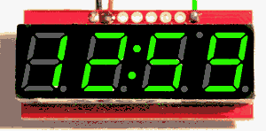
//Helo (Best stab we can make at "Hello"
//... followed by...
//12:59, standing for 12 minutes, 59 seconds...
//.. which will start counting down.
//12:58
//12:57... etc... at a little more than one
//count per second.
//Close the "doorbell" switch, and the time "counts" away much
//more quickly. It may not happen "immediately", but if you press
//AND HOLD the switch to have the "go fast" kick in quite soon.
//Likewise, there may be a slight lag after you release the switch
//before the countdown reverts to the slow rate.
//If the time reading is above 1:59 when
//you close the switch, the time drops to 1:59. (This to bring you
//closer the end-of-countdown features faster.
//During the last 40 seconds, the LED will flash.
//Then there's a "bang" substitute. And then it all starts again.
#include <NewSoftSerial.h>
//Yes, NEWSoftSerial...
//I don't think SoftwareSerial has the
//"available()" function, does it? Not
//needed here, but might as well stick
//to one library for all work with
//extra serial lines.
#define swGoFast 12//no ; here. Connect a switch here, momentary
//best, but toggle ok. Connect other side of switch to ground.
//No pull up resistor needed, the internal one will be used.
#define LEDpin 13//no ; here. Connect an LED here. Other side
//of it to current limiting resistor, and then that to ground.
//For a trivial added impact, you can add a buzzer on the same
//output pin. Wire it to make noise when the output is low.
#define SerInToArdu 2//no ; here. Not used in this demo,
// but in defining mySerialPort, we to designate some pin
// for the serial data into the Arduino.
#define SerOutFrmArdu 3//no ; The pin that serial data
// will go out from the Arduino on. Beware "Rx"/"Tx"
// "gotcha": The Arduino's "Tx" (transmit) will go to
// the connected device's "Rx" (receive).
#define wPowerOn 2000//no ; here. Delay while powering up.
//From AFTER "HELO" put on module until first time appears
//Also used at end of each full countdown.
#define wSlowSecond 600//no ; here. Nominally "a second"...
//A bit less than a second to make demo move along. Set to
//1000 if you want countdown to proceed in real time.
#define wFastSecond 55//no ; here. Time for "a second" when
//program running quickly.
byte bMinTen;
byte bMinUni;
byte bSecTen;
byte bSecUni;
boolean boFirstPass=true;
boolean boGoFast=false;
word wHowFast=wSlowSecond;
NewSoftSerial mySerialPort(SerInToArdu,SerOutFrmArdu);
//Creates the serial channel we will use.
//================================ SETUP()
void setup(){
pinMode(LEDpin,OUTPUT);
digitalWrite(LEDpin,HIGH);
digitalWrite(swGoFast,HIGH);//Connect internal pull up to
//this pin which, by default, is an input.
pinMode(SerOutFrmArdu,OUTPUT);
pinMode(SerInToArdu,INPUT);//Not actually needed... put in
//to be explicit as to data direction over serial lines
mySerialPort.begin(9600);
mySerialPort.print("v");//To reset display module
//"Reset cursor": Until you send the module a "v", it keeps track
//of how many characters it has received since power on... which
//may be longer ago that since you last reset your Arduino.
//If you reset the Arduino at a "bad" moment, which has roughly a
//3-in-4 chance of happening, the next time the Arduino sends something
//the module won't use it as you intended. Suppose your program is just
//sending 1234,1234,1234... to the module. And you reset between the
//sending of the 1 and the 2. When the Arduino finishes rebooting,
//if you aren't sending the "v" as part of setup, the module will
//display 4123, because, as far as it's concerned, the Arduino is
//sending 4123,4123,4123...
//The module isn't sent, and doesn't require any "end of line" indicator.
//It already had a "1" when the Arduino was reset, and then it received
//a 1234. For a moment, the module would be displaying 1123.
//Then it would receive a 4, but treat it as the first character of
//the next block of 4. And then a 123, as the second, third, fourth
//characters to be displayed, so you would see 4123. The next 4 received
//would be seen as the character for the left hand character in the next
//thing to display, and thus you see 4123, 4123, 4123...
};//end "setup()"
//================================= LOOP()
void loop(){
if (digitalRead(swGoFast)==LOW){
boGoFast=true;
wHowFast=wFastSecond;
}
else{
boGoFast=false;
wHowFast=wSlowSecond;
}
//boFirstPass is true on the first pass through "loop()", AND
//on the first pass through it after the countdown reached 00:00
if (boFirstPass) {
mySerialPort.print("w");//This plus next turns off all dots.
//N.B.: Sending a character this way sends only 8 bits...what we want.
mySerialPort.print(B00000000,BYTE);
//Old Skul. Try mySerialPort.print(0b00000000);today.
// 8 0s or 1s after the b. Not more, not less.
//If trying to send zero, you may STILL have a problem...
// For zero, create a byte-type variable, put zero in
// it (byte bZero=0;), and print THAT...
// mySerialPort.print(bZero);
//N.B.: Sending a "B-formatted" number seems to send more than
//8 bits... or SOMETHING happens that doesn't if the ",BYTE"
//part is included.
mySerialPort.print("HELO");
delay(wPowerOn);
delay(wPowerOn);
mySerialPort.print("xxxx");//Blank display... for
delay(wSlowSecond);//..several "second"s
delay(wSlowSecond);
delay(wSlowSecond);
mySerialPort.print("w");//Command, "Turn dots on..."
mySerialPort.print(B00010000,BYTE);//Blank display... for
boFirstPass=false;
bMinTen=1;//Set up start time as 12:59...
bMinUni=2;
bSecTen=5;
bSecUni=9;
};//End of stuff done only at start of countdown
mySerialPort.print(bMinTen);//Send digits of time to display
mySerialPort.print(bMinUni);
mySerialPort.print(bSecTen);
mySerialPort.print(bSecUni);
delay(wHowFast);
DecrementTime();
if((bMinTen*1000+bMinUni*100+bSecTen*10+bSecUni>159)&&(boGoFast)) JumpAhead();
//Yes.. that IS strange.. it turns 12 minutes, 59 seconds into 1,259....
// but that was "enough" for my purposes, so why do anything fancier?
if(bMinTen*1000+bMinUni*100+bSecTen*10+bSecUni<41) NearZero();
if(bMinTen+bMinUni+bSecTen+bSecUni==0) GoBang();
};//end "loop()"
//===================
void DecrementTime(){
if (bSecUni>0)
bSecUni--;
else
bSecUni=9;
if (bSecUni==9)
if (bSecTen>0)
bSecTen--;
else
bSecTen=5;
if ((bSecTen==5)&&(bSecUni==9))
if (bMinUni>0)
bMinUni--;
else
bMinUni=9;
if ((bMinUni==9)&&(bSecTen==5)&&(bSecUni==9))
if (bMinTen>0)
bMinTen--;
else
boFirstPass=true;
};//end DecrementTime
//==============
void NearZero(){
//Things we do when countdown nearly finished
if (bSecUni & 1){//true when bSecUni odd... or is it even? One or other!
digitalWrite(LEDpin,HIGH);}
else {
digitalWrite(LEDpin,LOW);};
};//end NearZero
//============
void JumpAhead(){
bMinTen=0;
bMinUni=1;
bSecTen=5;
bSecUni=9;
};//end JumpAhead
//============
void GoBang(){
//"Special effects" for when countdown reaches zero.
//Pretty boring at the moment, could be more fun.
//You are not restricted to 0-9, blank, hyphen.
//You can set ANY combination of segments on/ Segments off.
//See module's datasheet...
//http://www.sparkfun.com/datasheets/Components/LED/7-Segment/SFE-0012-DS-7segmentSerial-v41.pdf
mySerialPort.print("w");//This plus next turns off all dots.
mySerialPort.print(B00000000,BYTE);
digitalWrite(LEDpin,HIGH);//Turn LED (and buzzer) off.
mySerialPort.print("xxxx");//"x": all segments of character off
delay(1200);
mySerialPort.print("-xxx");
delay(800);
mySerialPort.print("xxxx");
delay(800);
mySerialPort.print("x-xx");
delay(800);
mySerialPort.print("xxxx");
delay(300);
mySerialPort.print("xx-x");
delay(800);
mySerialPort.print("xxxx");
delay(300);
mySerialPort.print("xxx-");
delay(800);
mySerialPort.print("xxxx");
delay(1000);
for (byte bTmp=5; bTmp--; bTmp>0){
mySerialPort.print("8888");
digitalWrite(LEDpin,LOW);
delay(100);
mySerialPort.print("xxxx");
digitalWrite(LEDpin,HIGH);
delay(300);
}
delay(wPowerOn);
};//end GoBang
N.B.: Until further notice: Except for the "v" sent on its own at the start of the code, in setup(), Always send 4 characters at a time, as above... even if sometimes one or more of the characters was an "x" or a hyphen ("-").
Basics: The display can give you 0-9, and A-F.
Basic: If you want all 7 segments of a character off, send an "x" for that position.
Rather neat: The display doesn't care if you send it the number 2, or the character 2... you will get a 2 on the display either way.
A little fancier: While it can't give you every letter in both upper and lower case, it will give you many letters, and a hyphen ("-"). There's a table in the good documentation from Sparkfun.
Very fancy: In the "special codes" section I will show you how to put any combination of "on" and "off" segments on a given character of the display.
The dots.... Besides the four matrices of seven segments, the display also has a colon between the 2nd and 3rd digits, four decimal points, and a small dot at the top of the display, between the 3rd and 4th digits. (This last dot is called an "apostrophe"). Any combination of these dots can be on or off. The combination you require is accomplished by using one of the "special codes". (See next section.)
Let's get one thing out of the way: There is no easy way to scroll what is on the display. If you want people to see....
1234
2345
3456
4567....
... then you're going to have to do it "the hard way": By explicitly sending those codes to the display module.
Here's another thing we can get out of the way. Suppose you have 123 in a variable. There is no EASY way to put 123 on the LEDs. You have to convert the number 123 into four characters: A blank, a "1", a "2", and a "3". That's a story for another day.
I've said this before, but it bears repeating: One thing you must understand: From the time the module is powered up, it will normally receive bytes four at a time. It keeps track of how many it has received. If you had an Arduino program with the following at its heart.....
mySerialPort.print("123");
  delay(1000);
mySerialPort.print("456");
  delay(1000);
.... you would NOT see....
123
456
123
456...
... over and over again. (Each line representing the state of the display module for a second, before the display changed to the next.
You would see....
 123
(1234 very briefly, probably too briefly
    to perceive)
 5634
 3612
 3456
 1236...
... over and over. The unit (normally) just takes one byte after another, and places them on the display, going to position 1,2,3,4,1,2,3,4,1,2,3,4.... etc in rotation. ("1" being the left hand column.) What you're seeing at any one time in the example above is a mixture of one old digit, and three freshly "printed" ones... but the new ones are in different places on different lines.
If, before you have sent anything, or after the 4th, or 8th, or 16th... etc. "normal" character, you send one of the 8 special codes (list in a moment), then the unit will expect you to send one more character (to "go with" the special code), and it will then go back to watching for either a block of 4 normal characters, e.g. 1234, or another 2 byte command via special code. (Unless you send the "v" special code, which will normally be on it's own, with no "goes with" second character. (The exception to the exception!))
It is not, except for the "v", a good idea to send a "special code" in the middle of a block of four "ordinary" characters.
Let's take a specific example.
If you send the module a "z" followed by an "A", you will change the brightness of the display to "not very bright". Send a "zz", and you will change the display brightness to something brighter than what "zA" gives you. (The case... capital or small, "A" or "a", matters here.
In fact, you'll be better off sending numbers rather than characters. Use a character for the "z", by all means, but after sending that, send a number. If you send zero, the display will be very, very dark. Send 254 after a "z", and you set the display to the brightest possible level.
Just before we move on: An important "detail": If you change the brightness setting for your display module, it will "remember" the setting, even if you turn the power off and then on again. So if your display used to be brighter, send it a "z" followed by 254 if you want it to be bright again.
Which brings me neatly to "How do we send the module 254?" This isn't the simple question you might hope.
In all that follows, the first thing your Arduino should send to the display module is....
mySerialPort.print("v");
I'll explain why in a while. For now, just do it. It "gets things started".
Bear with me for a bit... this is all going someplace. To get started, we'll go back to...
mySerialPort.print("1234");
... for a moment. THAT causes four numbers to be sent out over mySerialPort: 49,50,51,52. 49 is the code number assigned for the character "1" in ASCII (saying "ASCII code" is like saying "PIN number", when you mean personal identifier number).
If you use the following, you also get 1234 on the display module....
mySerialPort.print(1,BYTE);
  delay(1000);
mySerialPort.print(2,BYTE);
  delay(1000);
mySerialPort.print(3,BYTE);
  delay(1000);
mySerialPort.print(4,BYTE);
  delay(1000);
(The delays are there to show you that the module displays the "1" immediately... it doesn't wait until all four numbers have arrived.)
You can't say....
mySerialPort.print(1,2,3,4);
... because the Arduino will send the four numbers as 16 bit numbers, and you need them sent as 8 bit numbers
You can't say...
mySerialPort.print(1,BYTE,2,BYTE,3,BYTE,4,BYTE);
... because "print" isn't clever enough to manage that.
Note: We are seeing an example of what I said earlier: The module is clever enough to "know" to put a "1" on the display, regardless of whether you sent it the number 1, as we have just been doing, or if we send it the character "1" by sending the ASCII for "1" as we were doing earlier, i.e. sending 49, which we get the Arduino to work out for us by saying....
mySerialPort.print("1");
Note that I am using quote marks ("), not apostrophes ('). (Apostrophes indicate single characters. By using the quote marks, we are signaling that we are supplying a string of characters.)
Just one more way of sending 1234, and then we move on to using this tedious esoterica...
We're going to do almost...
mySerialPort.print(1,BYTE);
  delay(1000);
mySerialPort.print(2,BYTE);
  delay(1000);
mySerialPort.print(3,BYTE);
  delay(1000);
mySerialPort.print(4,BYTE);
  delay(1000);
... again. But here it is done a new way....
mySerialPort.print(B00000001,BYTE);// sends 1
  delay(1000);
mySerialPort.print(B00000010,BYTE);// sends 2
  delay(1000);
mySerialPort.print(B00000011,BYTE);// sends 3
  delay(1000);
mySerialPort.print(B00000100,BYTE);// sends 4
  delay(1000);
00000010 is what we usually call "two"... i.e. the number of eyes most humans have... written in binary. If we wish to write numbers in binary in our Arduino code, then we have only to prefix the 1's and 0's with a B.
While we're on the subjects of ways to show numbers: The datasheet frequently uses "numbers" which start "0". When they write something like 0x77, or 0x7F, they are expressing something "in hex". 0x77 and 0x7F happen to be what we'd normally call 119 and 127. They can be written in binary as B01110111 and B01111111. We don't need hex here, so be glad I wrote that out of this for you!
WHAT's ALL THAT GOOD FOR??
At last we get to a new "special code". Which we need to know about binary representation to use.
If you send....
mySerialPort.print("w");
mySerialPort.print(B00000000,BYTE);
... you will turn off any of the display modules "dots" that may be on. You will turn off the colon, the apostrophe, the 4 decimal points.
Send....
mySerialPort.print("w");
mySerialPort.print(B00100000,BYTE);
... and you will turn on the "dot" LED at the top of the display, between the 3rd and 4th digits. This is the dot the documentation calls the apostrophe.
Each bit (binary digit )(1 or 0) in the number sent to the display after the special code "w" determines the state of one of the dots (or the pair of dots making the colon between the second and third characters) on the display. There's a guide in the documentation as to which bit controls which dot... but you have to know how the bits are numbered. They are numbered from right to left, and the first is "bit 0". Thus the apostrophe's bit is bit 5. Bits 6 & 7 control nothing; sending B00111111 would turn all the dots on. Use B00010000 to turn just the colon on, to make the display look right for showing minutes:seconds, or hours:minutes.
So! That's the "z" (brightness) and "w" (dots) codes out of the way.
We've sort of met the "v" code before. But I didn't really explain it. The module does not always respond well if you "mix" ordinary "display this" signals, like a 1,2,3 or 4, etc, and any of the "Special" codes. With the exception of the "v" code, it is always best to send multiples of FOUR "display this" codes, only sending "Special" codes as the 5th, 9th, etc thing sent to the module. Unless you remove and restore the power to your LED display module, you have not reset it.... even if you have reset your Arduino. The "v" special code gets us out of the potential jam.
When the display module receives a "v", it "starts it's counting" again, treating the next character received as the first of a block of 4 things to display, or a "Special" code, which, in every case except a "v" must be followed by a second byte, which is the argument to the command. For example, the byte following a "z" says how bright the display should be.
In some places in this essay, I've suggested that you send two v's whenever you send one. That now seems illogical to me... one should do. (But two will do no harm!)
If you send a 127 (I can't do that one with anything like "z" or "v") to the display module, you will change the device's baud rate. You will change it's assumption about what speed you are sending it serial data. Happily, if you accidentally send a 127, unless the next byte is 0,1,2,3,4,5 or 6, the command to change the baud rate expectations has no effect. (You have only 6 chances in 256 of upsetting things with an accidental 127!). If you've upset the baud rate, you will have to find the baud rate the device is using, by trial and error, probably, before you can communicate with it again. And this is another setting that survives the power going off, then on again. The settings are...
Byte after a       Baud rate
127 Special Code   established

  0  - - - - - - - -   2400
  1                    4800
  2  - - - - - - - -   9600 (Arduino default speed)
  3                   14400
  4  - - - - - - - -  19200
  5                   38400
  6  - - - - - - - -  57600
With the remaining Special Codes, "{", "|", "}" and "~", aka (decimal) 123,124,125,126, you can turn on (and off) precisely the combinations of segments of your heart's desire in character 1,2 3 and 4 respectively, numbering the characters from the left.
The following blanks all four characters, and then turns the just the three horizontal elements of the first character on, leaving everything else still off.
mySerialPort.print("xxxx");
mySerialPort.print(123,BYTE);
mySerialPort.print(B01001001,BYTE);
If you study the following, it may help you see how to use these codes. At the heart of it: Using a special code does not act as a substitute for an "ordinary" "print this"... it REPLACES something printed earlier with one of the four characters in an ordinary block of four.
mySerialPort.print("8888");
mySerialPort.print(123,BYTE);
mySerialPort.print(B01001001,BYTE);
delay(1000);
//At this point: 8s in most positions, but in
//the first, all the horizontal elements on
mySerialPort.print("xxxx");
mySerialPort.print(124,BYTE);
mySerialPort.print(B00110110,BYTE);
mySerialPort.print(125,BYTE);
mySerialPort.print(B00110110,BYTE);
delay(1000);
//At this point: nothing in most positions, but in
//the second, and third, all the vertical elements on
If you number the bits of the binary number in the conventional way, 76543210, then the bits control individual LEDs in the 7 segment character as follows:
Bit  LED
7   Bit not used
6   middle horizontal
5   top left vertical
4   bottom left vertical
3   bottom horizontal
2   bottom right vertical
1   top right vertical
0   top horizontal
Putting that another way....
       0
    5     1
       6
    4     2
       3
Sorry... I have to leave this here for now...
I'll try to write the following up "properly", but in the meantime...
How should you start with a new module? Just connect your Vcc (e.g. 5v. Anything down to 2.6 volts is acceptable) and ground. (The module will operate properly with Vcc down to 2.6 volts, so don't despair if you are using a 3.3v Arduino, or other microcontroller.) Don't (yet) connect anything else. You should see "0000" on the display. After you have confirmed that the new module displays the default "0000" nicely, connect a wire between the "Rx" pad of the display module to an output from whatever you are using to send things for display to the module. Don't be caught by the usual "newbie gotcha" in the naming conventions: The signal out of the controller will be transmitted (Tx) from the controller, received (Rx) at the display module. The signal on the data line should not rise above Vcc by more than 0.5v at any time. YOU CANNOT CONNECT AN RS-232 SERIAL SIGNAL DIRECTLY TO ONE OF THESE MODULES. See the information on the Wulfden PA4B in the "Hardware" section of my page about the serial port, if you need to know more about how RS-232 isn't synonymous with "serial".
If you find that your display isn't as bright as it once was, you probably inadvertently sent it a "z" command... which sets the display's brightness. The setting is carried over power cycle events.
What are the two rows of 8 long pins? They come from the LED module which is soldered to the small PCB which has the Atmel on it. (The 6mm square bit of black plastic with legs). the 16 long pins are, as far as I know useless... but I haven't dared trim mine off yet because I can't think why Sparkfun would have refrained from doing so if there was no reason not to. They are NOT alternate ways to connect the Vcc, Ground and Rx wires to your module.
Which way is "up"? The row of 8 pads (Rx, CSN, etc) run across the top of the display module
I hope that saved you the hours it took me to get past some of the newbie gotchas? Do please write in and tell me if bits were unclear, or you would like other aspects of these displays explained. If you have written something similar for people wanting to connect to the module via the SPI alternative interface, send me the URL of your page, and I'll consider giving you a link. Links from your page to mine appreciated, of course.
You are welcome to use the material here free of charge. But if you want to show your appreciation, you easily can make a gift to me or contribute to a charity I would like to help... I've listed several to choose from. (The link will open in a new tab or window.)
![]() Page tested for compliance with INDUSTRY (not MS-only) standards, using the free, publicly accessible validator at validator.w3.org
Page tested for compliance with INDUSTRY (not MS-only) standards, using the free, publicly accessible validator at validator.w3.org
....... P a g e . . . E n d s .....