 Recommend to StumbleUpon
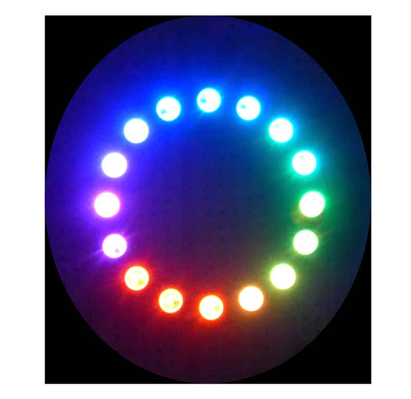
Too cool for words! Or should I say "Hot"? The static image doesn't begin to show you how cool this is. Each of the 16 pixels can be any color, bight, dim, or off, and you can change the states of all the pixels many times a second. Go on, get one... $10!... and try out your pattern ideas. Or use it to, say, make a visual indicator for the magnitude of some important parameter in whatever project you are working on just now.
If you only want "the highlights" there is a "summary" version of this page: Quick notes- Using WS2812 Smart LEDs/ NeoPixels.
The WS2812 is small SMT device. Cuboid, 5mm x 5mm x 2mm thick. (There are 16 of them, on a PCB, on the ring photographed to the left.)
In each: 3 very bright LEDs, and some "silicon brains". Hook a few together with just three wires: power, ground, and a data line, and you're all set for some fun.
Don't let the "SMT" worry you... many suppliers will sell you the devices already made up into a strip of connected WS2812s, or multiple WS2812s in a circle, or a grid of pixels. And there's still just three wires to connect to control all of the WS2812s in the package.
Pololu sells a ring of 16 for $10. Sparkfun will sell you strips of various specifications and lengths... if you've won the pools, how about a 5m weatherproofed strip with 300 WS2812s? ($119, sigh). (Shop carefully... not least, the WS2812s / meter count varies considerably between different suppliers. There are some guides out there.)
Sparkfun also sells rings, and Pololu strips... I was just giving you some examples of what's available.
This page is just some of the basics, to help you get started. After that, isn't much more to learn about the WS2812s and how they work... but to get the most out of them, you'll need a good imagination for graphics effects, and some programming skill to bring your concept to life... but the WS2812s at the heart of it will be as simple as ever.
You can download a few example programs from a Github repository I set up for that. Nothing very fancy, but some "grist" for a beginner's "mill". Worth at least what it will cost you. (Nothing.)
Shopping list: The obvious, and the not so obvious...
Detail: I'm going to speak of "strip" in all that follows, as if your smart LEDs are, as may well be the case, connected in a linear array. That is not by any means the only possible configuration. My own "strip", in fact, is a "strip" of 16, bent around to make a circle. But the LEDs in that circle are still numbered, addressed, 0 to 15. There are also arrays available in the marketplace in which you have multiple straight rows of LEDs, one above the other, as if, say, a strip of 30 has been "chopped" into 6 strips of 5, and laid out in a 5x6 grid. (With many of the strips on the market, and some wire, you could do just that with a linear array of 30) However, as far as the basic LED driving software is concerned, you would still be dealing with a "strip" of LEDs numbered 0 to 29. (Of course it would be easy and wise to create a little subroutine to accept x,y coordinates, and spit out a "strip address".)
By the way, these work fine on a NoviceGuard daughter board, NG_PwrDemand_2. I've even done a page about the details.
One of the Adafruit tutorials says...
IMPORTANT: To reduce NeoPixel burnout risk, add
1000 uF capacitor across pixel power leads,
add 300 - 500 Ohm resistor on first pixel's data
input and minimize distance between Arduino and
first pixel.  Avoid connecting on a live circuit
...if you must, connect GND first.
(Note the advice in the "warning", just above here on the page. Other than that....)
From now on, I am going to use "LEDs" quite often to refer to WS2812s. Of course, each WS2812 contains three LEDs, but usually when I say "the LED", I will be meaning "the module containing a red, a blue and a green LED". I think it will be easy to see from the context when I am speaking of the constituent LEDs.
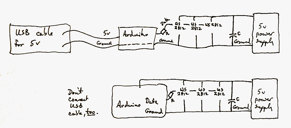
To hook your computer up to a string of WS2812s, you only need three wires...
A string of the devices, even one with "only" 16 of them, needs a source of 5v capable of delivering significant current. A 16 LED string can draw 800mA.
Not a "big problem"... but don't try to run the string off of the 5v made on an Arduino which has it's own voltage regulator circuits.
The following shows two alternative hook-ups. Do not connect the Arduino both to 5v via the USB cable and via the Vcc pin. One or the other.
The top circuit is convenient while you are programming the Arduino with whatever your imagination has come up with, and the second is fine, once programming is done. There's no need to have the USB cable connected at that stage, as long as you give the Arduino power from somewhere, and you might as well use the 5v that is powering the LEDs.
The capacitor, C, and resistor, R, are the ones mentioned in the highlighted warning at the top of this essay.
Isn't that a sweet, simple scheme! One data wire, and 300 or more WS2812s all "dancing" to the tune played by the Arduino. The Arduino, essentially, sends a separate message to each WS2812 (very quickly!). The message says how bright the modules red LED should be, how bright its green LED, how bright its blue LED. And then each WS2812 remembers what it was told until it hears otherwise from the Arduino. (It won't remember what it had been set to previously across a power on/off/on event.)
The slight "penalty" you must pay is that the Arduino has to use 3 bytes of memory for each WS2812 in your array... but the details of that are taken care of for you behind the scenes.
You can, of course, use any of the Arduino's outputs to drive the data line, but if you use digital pin 6, you won't have to tweak the examples which come in the .zip I am going to recommend.
Before you can play with your WS2812s, I'm afraid there's a chore. You need to install the Adafruit_NeoPixel library in your Arduino programming environment. I know... I don't like installing "stuff" either, usually. In this case: Very well worth it!
Go to the github LED-strip-Arduino page, and click on the "Download .zip" button (over at right, Jan 2018). Don't be alarmed by the "Pololu" on the page if you are using WS2812 (or WS2811) smart LEDs from someplace else.
Install the library in the usual way*. It comes with some examples, in a folder called "examples", which should go in the same folder you put the .cpp and .h files in. (I will try to explain that in more detail if a few people Facebook "like" this page, and say they need the help. Until then a page I wrote about using another library may be of use.)
* "Install library in usual way"...
Hmmm. Around mid 2015, I found "they" had "improved" things. Now that I've got to grips with it, I like the "new" way. Details at... http://sheepdogguides.com/arduino/ar3ne1libs.htm. If you are NOT a trusting soul, there's advice for you there. If you are, and just want to get on with the SmartLEDs use the following. (Tested Oct 15).
Go to Github... link above. Downloaded the file. When I did it, it arrived as "Adafruit_NeoPixel-master.zip". Opened the zip. It was one folder, "Adafruit_NeoPixel-master", with "stuff" in it. Don't be confused by the fact that the .zip has in it a folder with the same name as the zip!
Open Arduino IDE, click on "Sketch", "Include Library", "Manage Libraries", "Add .ZIP Library"... and navigate to where the .zip file is on your machine. Click OK. Then Things Happen. Not my preferred solution, but I imagine the people behind it worked hard, meant well. Sigh. (and, as I say, you can use a different approach, if you are less trusting.)
Once you have done the setup describe above, you have a useful library available to you.
Just put....
#include <Adafruit_NeoPixel.h>
... at the head of a program you want to use to control WS2812 smart LEDs.
Once that's in place, you can do the following...
Decide which pin you are going to connect your string of WS2812s to. In the examples, the pin's number resides in the variable "PIN", but, to me, that isn't quite descriptive enough. I'm using "bLedStripPin" in my examples.
Digression: By the way... for later... you CAN have more than one strip connected to a single Arduino. You would use an output pin for each, and you would created more than one instance of the Adafruit_NeoPixel class. (I've explained in detail at the end.
----
Another digression, this one for people who haven't worked with declaring instances of a class before. (If you've used NewSoftSerial, you have!)Declaring a variable should hold no fears... though perhaps you haven't called it by that name before now.
Suppose I'm building a lighting detector device, and I want to keep track of the number of flashes of lightning detected. I would use a variable called iCountOfFlashes. And before I could do things like...
iCountOfFlashes=iCountOfFlashes+1;
... I would have to have a line like...
int iCountOfFlashes;
I might make that...
int iCountOfFlashes=0;
...to take care of starting it off holding zero, but in any case, that line (with or without the "=0") is called "declaring" the variable. You need it because when the compiler sees it it says "Oh, the programmer is going to be saving integer-type data, and I need to set aside a little memory for that."
So far so easy.
(At this point, people who already know about this sort of thing need to start reading again...)
When you work with libraries, you will often see things which look a bit like a variable declaration. In working with the Adafruit library for the smart LEDs, we will always have, once, something like...
Adafruit_NeoPixel xxx=Adafruit_NeoPixel(p1,p2,p3);
.. but you have to replace "xxx" and p1, p2, p3 as follows.
For xxx you put something made up by you, using the same rules as you use when naming a variable. For example, you can't use "delay"... that's a word the language is already using. The example programs use the word "strip", which, like "PIN" strikes me as too general. I will be using SmartLEDStrip in my examples.
(Forget the p1, p2, p3 for a moment).
See how...
Adafruit_NeoPixel SmartLEDStrip;
is a bit like
int iCountOfFlashes;
int and Adafruit_NeoPixel are words the system knows. (The latter word known, as long as you remembered to provide the #include <Adafruit_NeoPixel.h>, and have the library installed, as discussed above.)
And the iCountOfFlashes and SmartLEDStrip are words you are going to use to refer to an instance of an int / Adafruit_NeoPixel "thingie" ("object", in some frames of reference, "class" in others)
Now... the "=Adafruit_NeoPixel(p1,p2,p3)" part... still not worrying too much about the p1,p2,p3.
This is like the "=0" in "int iCountOfFlashes=0;". It gets the new Adafruit_NeoPixel-type object "going", with initial values... values determined by what you put in p1, p2 and p3. (It uses a function called Adafruit_NeoPixel to do this. A little confusing, maybe, but trust me... it works. (Confusing? Well, we've got "Adafruit_NeoPixel" meaning two things, but that's okay, as long as we use it in two contexts. The first use, on the left of the equals sign, tells us that we are creating an object of a certain type. the second use, on the right of the equals sign, calls a function which will return something of the right type for the declaration's needs. "They" (who wrote the library) could, I think, have used a different name for one or the other... but there is a certain elegance in the way they did things.
In place of p1, you put the number of smart LEDs present in your strip. ("p" for "parameter", by the way.)
In place of p2, you put the number of the pin you are going to use to send instructions to the smart LEDs. The Adafruit library examples use pin 6, which will do fine, unless you have a reason to use a different one.
In place of p3, you put an arcane code suitable to the exact nature of the smart LEDs you are using. I'll explain in a moment, but first another digression.
You can skip to the next Good Stuff if you wish.)
I may make myself sound like an idiot, but here are some of the things I did to my Pololu 16 LED ring and associated components before finally getting it all set up right...
I had the power to my Arduino Pro Mini coming from the USB cable, thank heavens. And powered the LED ring from a separate 2 amp switched mode supply. Little whoopsie: I mis-wired the power connector, and applied the 5v (from a strong source) backwards. Yep. 5v to ground, and ground to the place that should have seen 5v. Ring didn't work. Supply got hot and smelly. Probably had it connected thus for as long as 5 minutes. What a stupid, stupid mistake! Why didn't I put my voltmeter on the two wires from the supply before hooking up?? Had I fried psu? ring? My Arduino, or at least a pin on it?? Apparently: No! (Though all are now marked to remind me that they may not be 100% reliable, due to the abuse they have suffered. They should be dead!
Then there's the little matter of the wire from the Arduino's ground to the LED strip's ground. That was loose. Not sure for how long.
I hadn't seen the "use resistor and capacitor" warning before finishing early experiments.
And last but not least... and to get back to the guide I was writing... I hadn't notice that the third parameter in the object declaration needs to be tweaked for the LEDs you have. I was lucky... the example came with the value I needed already present. But had the wrong value been present, I might have concluded that my ring was fried, when in fact it seems to have survived the abuse I've given it?
Oh... and several hours in, I discover that I've been running the strandtest example configured for a string of 60 LEDs (pixels), when I have only 16. It still ran! It gave pretty output! I'm looking forward to how much better it can be with the right value in the "how many LEDs" parameter!
So... who says fools have no patron saint watching over them? And who says there's no reason to be grateful in the world?
Anyway. End of digression.
-----------------------------
You need a number. But you will probably never know the number! With the library, you are supplied with a few constants. You pick one from each of the following two groups...
**LED type...
800 KHz bitstream (most NeoPixel products w/WS2812 LEDs)- use NEO_KHZ800 400 KHz bitstream (classic 'v1' (not v2) FLORA pixels, WS2811 drivers)- use NEO_KHZ400
**How they are wired...
LED units wired for GRB bitstream (most NeoPixel products)- use NEO_GRB LED units wired for RGB bitstream (v1 FLORA pixels, not v2)- use NEO_RGB
... and then you add the two. I had NeoPixel WS2812s wired for GRB, so I needed....
NEO_GRB + NEO_KHZ800
... as my third parameter.
----
Whew! Not hard, really. But some of the details above could trip you up.
So far we haven't got to actually turning on any LED. Soon!
So... from the above, if you've got the library installed, you've provided the resistor and capacitor, and if...
... then the start of your program should look like this...
//SmartLEDSimple1
#include <Adafruit_NeoPixel.h>

#define bLedSmartLEDStripPin 6//no ; here

Adafruit_NeoPixel SmartLEDStrip=
         Adafruit_NeoPixel(16,
         bLedSmartLEDStripPin,
         NEO_GRB + NEO_KHZ800);

void setup() {
  SmartLEDStrip.begin();
  SmartLEDStrip.show(); // Initialize all pixels to 'off'
}

void loop() {

  //TO COME!!...

}
Whew! When I started this, I thought it would be just a few minutes work. Little did I realize how many details I'd got right just from experience. Nothing "hard" in the above. But some ways to go wrong, if you are new to parts of this.
So! Now we have things in place... let's DO SOMETHING with our strip.
The examples are full of Good Stuff which is much more fun than the following... but here are the basics behind the fun programs...
======
Put the following in loop....
void loop() {
  SmartLEDStrip.setPixelColor(0,SmartLEDStrip.Color(255,0,0));
  SmartLEDStrip.setPixelColor(1,SmartLEDStrip.Color(255,0,0));
  SmartLEDStrip.setPixelColor(2,SmartLEDStrip.Color(0,255,0));
  SmartLEDStrip.setPixelColor(3,SmartLEDStrip.Color(0,0,255));
  SmartLEDStrip.setPixelColor(4,SmartLEDStrip.Color(0,0,255));
  SmartLEDStrip.setPixelColor(5,SmartLEDStrip.Color(0,0,255));
  SmartLEDStrip.show();//****
  delay(1000);
}
We'll go through that from the bottom up...
The delay(1000); doesn't make any difference to what you see in this example... but it does save your system from "thrash", which I hope you see. And if you don't, don't worry about it!
The SmartLEDStrip.show(); is vital.Without it, you will see nothing! I'll come back to that.
The first six lines in loop() say "make the color on the first, second, third... last" of six pixels red, red, green, blue, blue and blue, respectively.
It is a pretty boring result. But it is useful...
We made two LEDs red, one green, three blue so that we could tell which was the first. (We might have been confused about what color a given triad of numbers would produce. But we know from our code that the color that two LEDs show results from the numbers we sent to LEDs 0 and 1.
(Note that while the LEDs are "named" (or addressed) from ZERO, they are COUNTED the way humans count. In the line...
Adafruit_NeoPixel SmartLEDStrip=
         Adafruit_NeoPixel(16,
         bLedSmartLEDStripPin,
         NEO_GRB + NEO_KHZ800);
... you put 16 if you have 16 LEDs. (Not 15, the address of the last one.)
A detail, something you probably already know...
In the code, we have...
SmartLEDStrip.Color(0,0,255)
There's a function called "Color" which returns a correctly organized single number from any three numbers passed to it. (Those numbers should be in the range 0-255, inclusive.)
By the way that is written, we know that "Color" is provided for us within the object SmartLEDStrip, of type (or class) Adafruit_NeoPixel. We provided ourselves with that object, and the functions which come with it, with the "Adafruit_NeoPixel... line we inserted.
===
Back to the SmartLEDStrip.show();...
We didn't actually change the color of the LED when we did, say,...
SmartLEDStrip.setPixelColor(0,SmartLEDStrip.Color(255,0,0));
We merely changed the entry in a table inside the Arduino.
Only when we did the SmartLEDStrip.show(); did anything get sent to the LEDs themselves.
To repeat what I just said, sort of...
The software which you "turned on" and incorporated when you set up the SmartLEDStrip object sets aside some memory. There are a few "header" things to keep track of (like how many LEDs in the strip), and then the software needs three bytes for each WS2812 (or 2811) in the strip. When you do a .setPixelColor() you are only changing the values in the memory. It is when you do a .show() that the values from the memory are sent to the three LEDs (one red, one blue, one green) in the WS2812. The WS2812 also takes care of remembering the last red/ green/ blue values sent to it. If you don't think that's pretty cool, try writing software to make digits appear on a "dumb" seven segment LED display, i.e. one that can show the digits 0-9 and a few letters, if you don't mind them being a little crude. The capabilities of the WS2812 ARE cool!
Remember we did a .show() during setup()? And that after that all the LEDs were off? That tells us that when we created the Adafruit_NeoPixel0-type object called SmartLEDStrip, part of the process was to put a zero in all of the bytes of memory. Makes sense. Let's us start with a known state.
Want "proof" that things work as I say?
Put a .show(); and a delay(600); after each of the .setPixelColor() lines.
Now when the program starts, you will get the first LED, then a delay, then the second, then a delay, etc. Of course, once you've passed through loop() once, you won't see any further changes....
Until you write a more interesting program! You now have the basic tools. You know how to wire up the device. You know what needs to go into setup(). And you know how to use setPixelColor and the .Color function.
The rest is just clever programming!
By all means run the demos. Particularly strandtest... it produces very pretty results.
And when you've done that, go and write something interesting or fun or maybe both... and post a note about your project at the Arduino Playground.
That tells you what you need to get going with WS2812-based arrays. While I was working on this, I was inspired to write a separate tutorial about a simple control structure you might employ, but you don't need that to play with your WS2812s.
Once you've got yourself started... or maybe to encourage you to get started, there is a Google Community dedicated to these neat little devices. (My thanks to the poster at the Arduino forum who brought this to my attention.)
Remember I said you could hook up more than one string of WS2812s?
This is how you would do it. I'm afraid this is untested. Send me a free WS2812 array and I will test the following and fix any flaws. But it should Just Work... or work with little tweaking...
//SmartLEDSimple1
#include <Adafruit_NeoPixel.h>

#define bLedSmartLEDStrip0Pin 6//no ; here
#define bLedSmartLEDStrip1Pin 7//no ; here

Adafruit_NeoPixel SmartLEDStrip0=
         Adafruit_NeoPixel(16,
         bLedSmartLEDStrip0Pin,
         NEO_GRB + NEO_KHZ800);

Adafruit_NeoPixel SmartLEDStrip1=
         Adafruit_NeoPixel(16,
         bLedSmartLEDStrip0Pin,
         NEO_GRB + NEO_KHZ800);

void setup() {
  SmartLEDStrip0.begin();
  SmartLEDStrip0.show(); // Initialize all pixels to 'off'
  SmartLEDStrip1.begin();
  SmartLEDStrip1.show(); // Initialize all pixels to 'off'
}

void loop() {
  SmartLEDStrip0.setPixelColor(0,SmartLEDStrip.Color(255,0,0));
  SmartLEDStrip1.setPixelColor(0,SmartLEDStrip.Color(0,255,0));

  SmartLEDStrip0.show();
  SmartLEDStrip1.show();

  delay(1000);
}
That would make the first LED on the strip connected to pin 6 bright red, and the first LED on the strip connected to pin 7 bright green. Not very exciting!... but it shows how to use two strips, I hope?
![]() Page tested for compliance with INDUSTRY (not MS-only) standards, using the free, publicly accessible validator at validator.w3.org. Mostly passes. There were two "unknown attributes" in Google+ button code, and two further "wrong" things in the Google Translate code. Sigh.
Page tested for compliance with INDUSTRY (not MS-only) standards, using the free, publicly accessible validator at validator.w3.org. Mostly passes. There were two "unknown attributes" in Google+ button code, and two further "wrong" things in the Google Translate code. Sigh.
....... P a g e . . . E n d s .....