 Bookmark this on Delicious
 Recommend to StumbleUpon
If you are an experienced Arduino (or other microprocessor user), you may prefer the "nutshell" version of this guide to a simple LCD+keypad shield.
This way to attach an attractive backlit LCD screen with two rows of 16 characters to an Arduino or similar may not be the cheapest, but it isn't expensive, either ($12 or £11 in Dec 14) and it also offers 5 input buttons which only need one input channel to the Arduino to service them. Go on. Spend a little money, save some time. It will give you time to do something more interesting!
Maybe you've already bought one of these devices? Plugged it into an Arduino, as a shield, i.e. piggyback? If you have, I hope you didn't "mess with" the signal on the Arduino's D10 pin yet? When an Arduino is reset, all the I/O pins come up configured as inputs. As long as your D10 pin remains configured as an input, you will be okay. More on how to use D10 to turn the backlight on and off is presented at the bottom of this essay.
I've tried to write a page for you to make it easy even for novices to enjoy the LCD / Keypad shield from Hobbytronics.co.uk and DFRobot.com. I have no connection with Hobbytronics or DFRobot or anyone associated with the shield, other than as a "happy customer" of Hobbytronics (I've never had anything to do with DFRobot.) £11 inc taxes, but not p&p. If it would be easier for you to order this from the USA, DF Robot sells a very similar device for $12 (Dec14. That is excl p&p). (Actually, to be fair, it the device probably originates at DFRobot, but I met it on the Hobbytronics page, and had written all of this introduction before becoming aware of the DFRobotics device.)
Don't let the word "shield" scare you. I'm going to show you how to use it "independently", with your Arduino in one breadboard, and you Hobbytronics LCD/ Keypad module in a second breadboard, and just 9 wires between the breadboards for those who don't want to "piggyback" it on their Arduino, or who are perhaps using one of the many devices with a different footprint than the Uno, which is the footprint you need to "piggyback" this, to use it as a shield. (I sometimes call those wires "jumpers" in what follows.)
I'm no expert, and haven't tested the product extensively, but to me it seems well designed and well made. And I have "tested" it to the extent that I have tried out all of the various features discussed below.
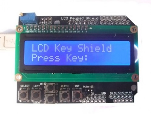
The DFRobotics/ Hobbytronics LCD Keypad shield gives you a neat, tidy board (6cm x 8cm) which you can plug "piggyback" onto an Uno, Diecimila, Duemilanove or Freeduino. I.e., for those it is a shield. For other boards, including other microprocessors, if you adapt an LCD driver for the board of your choice, you can connect it with just a few jumper wires. (You can, of course, also use it that way with an Uno, etc.)
Don't be fooled by the concise version of the name. The keypad and the Liquid Crystal Display are quite separate features. They just happen to share one PCB. You canuse just one or the other, if you wish. The board gives you....
(If you are using it as a shield, you will find a second "reset" button provided on the shield, wired in parallel with the board's reset button. This doesn't "add" anything, but it makes doing an ordinary reset mechanically easier.)
The contrast of the writing on the LCD's screen can be adjusted with a simple multi-turn pot which is on the board.
Besides the connections already indicated, you have to connect the board's ground to the driving microprocessor's ground and supply the board with 5v which also shares its ground with the microprocessor. (If used as a shield, all of these matters are taken care of for you. The board will draw its 5v from the Arduino it is plugged into.)
I was born under the "if there's a hard way, why use the easy way?" star, and am a pessimist to boot. I have a strong feeling that the shield works Just Fine as a shield. But in my testing, I had it plugged into a separate breadboard and only connected the wires I wanted to connect.
Yes, I know, real geeks don't need manuals, but if you have one of these devices, at least be a little cautious with pin D10 until you have looked into the issues associated with that. (Don't do anything in your software to change its default "pin is for an input to the Arduino" state.)
Another quick "you need this!" bit of information for the "try it now" brigade:
"The board uses different pins to the Arduino example
sketches, so to make the display work, use the
following sequence of pins when starting the library:

LiquidCrystal lcd(8,9,4,5,6,7);"
(I'll come back to using the LCD screen in a little while.)
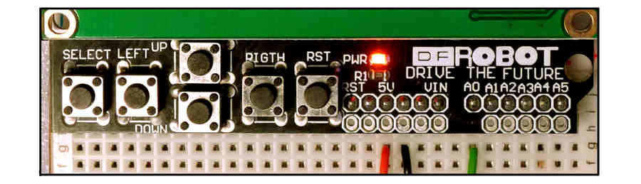
Start by JUST connecting the board's ground and 5v to the Arduino's ground and 5v. Ground to where you see the black wire in the image to the right; 5v to where you see the red wire. The image on the right is of the module's lower edge. (We'll come to the green wire in a moment.)
The small red LED marked "pwr" should come on. You can see it in the image. It is about half way across the board, slightly above, and just to the left of, the RST button.
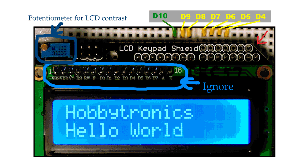
As supplied, my unit came up, on the LCD, with a row of solid rectangles across the top row, and an "invisible" row of rectangles the same color as the background (blue) across the bottom. If you aren't seeing this, or if the upper rectangles aren't white, try adjusting the pot, which should fix things for you. "The pot" (potentiometer) is on the "upper", left hand corner of the board. You can see it in the image below.(The board is turned as above and below for all of my descriptions.) The pot is the square "thing", about 1cm on a side, with a tiny screw (bolt, actually) head sticking out of it. You turn the bolt to adjust the pot. The followiong image is of the modules upper edge.
This is the only "adjustment" you can (easily) make to what the display looks like. And you can only do it by turning the small bolt... there is no software control of the panel's contrast, etc. Well. No simple software control. (Later we will see that you can "hide" all the writing on the display, and get it back again. And we can also turn the display's backlight on and off. These are two separate possibilities, although if you have turned off the backlight, you might want also to "blank" the display, so users aren't frustrated by faintly visible text.)
The module draws 25mA, regardless of how you have the pot set. I left the film of plastic protecting the screen of the LCD in place. It didn't degrade the display or lead to heat build up. (If, another time, you are having trouble with an LCD, with the protecting plastic in place, try looking under the plastic. Because of how LCDs work, the "wrong" sort of plastic would distort the display.)
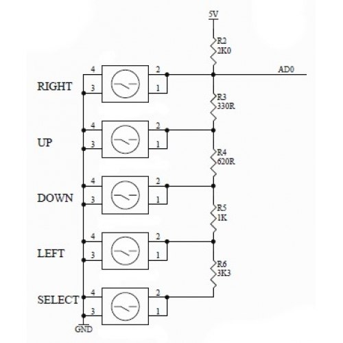
The circuit used for the 5 buttons making up the keypad is quite clever. But easy to use. It's a bit like paperclips: Anyone can use them, but wasn't the person who invented them clever?
Note: There are SIX buttons on the module. The one marked "RST" is simply wired to your Arduino's "ordinary" reset button, and if you press it, you will reset the Arduino. It is just there because if you are using the LCD / Keypad board as a shield, it becomes difficult to get at the Arduino's original reset button.
Four of the other five buttons are laid out and labeled "left", "right", "up" and "down", and you CAN use them for these functions... or anything else you want to use them for. The remaining, not- yet- discussed button is the one labeled "select".
By the clever circuit I alluded to before... and the fact that the Arduino has built-in ADCs (analog to digital converter circuits), you only need to use one of the Arduino's analog inputs to read all five buttons.
If you use the module as a shield, it will connect the five buttons to the "A0" input (On some diagrams, the pin I am talking about is marked "ADC7", but I am naming the pins as the programming language names them.)
If you are connecting the module to your Arduino with jumpers, you will need one from module's lower edge, the pin marked "A0", the 6th pin in from the lower right hand corner. (The pin with the green wire in the image above, the green wire near the red and black wires.) That wire will need to connect to the analog input of your choice on your Arduino. I would recommend that you choose to use A0, so that your programs won't need tinkering with, if you ever decide to plug the module in as a shield.
For the buttons to work, you also need the 5v and ground connections mentioned earlier.
You don't "need" it, but in case you want it, here (to the right) is the circuit used in the module, to connect the 5 buttons to one line.
The following simple little program watches the analog input, and displays the readings from it on the Arduino's serial monitor.
void setup()
{
  Serial.begin(9600);
  Serial.println("Welcome to HTronicsLcdKeypad");
  Serial.println("Visit sheepdogsoftware.co.uk for further useful stuff.");
  delay(1200);// Give reader a chance to see the
     //output on the serial monitor. (This program
     //doesn't use the module's LCD.)
 }

void loop()

{
int iAnReading;
iAnReading=analogRead(0);
Serial.println(iAnReading);
}
Set that running. Open up the serial monitor.
You should see a "river" of numbers rushing down the page. If no key was pressed on my system, the reading was 1020. You will probably get nearly the same numbers, but it might be an idea to check.
Pressing the other buttons... one at a time, by the way... should give you something like...
Select: 642
Left:   412
Up:     106
Down:   262
Right:    4
Once you know how to drive the module's LCD, you can, of course, present the "buttons line" readings to the user via the LCD.
If you are using the board as a shield, of course your life is relatively simple.
If you are connecting the Hobbytronics board to an Arduino with jumpers, it isn't a big hassle, just be careful to connect the right pins. You connect board to Arduino as follows. Be careful when counting to where you think a wire is... note (red arrow, upper right) that there is one pin with no associated pad.
Also... pay no attention to the markings on the PCB the LCD itself is on. (Marked "ignore" in my image.)
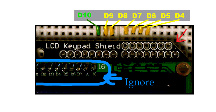
You don't need, yet, to connect the green wire to "D10". In fact I would suggest you wait to do that until you've read the material at the bottom about using that input to the LCD/Keypad module.
In addition to the yellow wire connections shown in the image, you need to connect the Hobbytronics board to 5v and ground, as already discussed above.
To put that another way: You need the following... (I will try to make a diagram of this in due course....)
You need to connect the D4 to D9 pins of the Arduino to the pins which would "mate" with them if you plugged the Hobbytronics module (HTM) into an Arduino Uno. I.e....
The 5th pin from the HM's upper right hand corner needs to go to the Arduino's D4
The 6th pin from the HTM's upper right hand corner needs to go to the Arduino's D5
The 7th pin from the HTM's upper right hand corner needs to go to the Arduino's D6
The 8th pin from the HTM's upper right hand corner needs to go to the Arduino's D7
The 9th pin from the HTM's upper right hand corner needs to go to the Arduino's D8
The 10th pin from the HTM's upper right hand corner needs to go to the Arduino's D9
Once you have the device hooked up, the following is a very basic "Hello World" you can try. We'll analyze it in a moment.
The "LiquidCrystal" library is a standard library, included with the basic Arduino development environment, at least it was part of the Arduino development environment version "0017".
// include the library code:
#include <LiquidCrystal.h>

// initialize the library with the numbers of the interface pins
LiquidCrystal lcd(8, 9, 4, 5, 6, 7);

void setup() {
  // set up the LCD's number of columns and rows:
  lcd.begin(16, 2);
  // Print a message to the LCD.
  lcd.setCursor(0,0);
  lcd.print("Hello World");
  lcd.setCursor(0,1);
  lcd.print("Hobbytronics");
}
By saying...
#include <LiquidCrystal.h>
... near the start of the code, we are telling the compiler to use some "extra bits" which are available to it in the library called LiquidCrystal, which, as I indicated a moment ago, should be there and ready for use on your system.
Next we have the line...
LiquidCrystal lcd(8, 9, 4, 5, 6, 7);
... outside, you may notice, either of the two subroutines which make up the program, outside setup() and loop(). Although the above line is not so very different from....
int iVal;
... which sets up, for the program's use, a variable called iVal.
The "LiquidCrystal..." line sets up something called "lcd", an entity named "lcd" (just as our variable was given the name iVal).
(Note: "LiquidCrystal" can be used several different ways, and sometimes (elsewhere) you will see it with a different number of numbers following it. Yes, for our purposes, it really is meant to be followed by 6 numbers.)
The "entity" ("lcd") is a bit fancier than a mere variable. And when we set it up, we had to tell the system "some stuff" (that's what the numbers are for. The integer variable didn't need any further "stuff" when it was being set up.
With a "thing" like "lcd", set up by LiquidCrystal, comes functions... "verbs", if you like, associated with the "thing", "lcd".
The point of the thing called lcd was that we control the actual LCD panel by lines in our program using the program entity "lcd". We write "lcd", put a dot after it, and a "verb" (defined within the LiquidCrystal library) after the dot. You'll see. In a moment....
Once we'd set up lcd, with the line shown earlier, we need to tell our software how many rows of characters there are in the particular bit of hardware we have attached, and also how many characters there are on each line. Our display has 2 lines of 16 characters, and (among other things) to "tell" the system about this, we put the following in the setup() subroutine, to be executed once, as the program is coming to life...
lcd.begin(16, 2);
After we'd done that, we could quite possibly just use....
lcd.print("Hello World");
... but to be thorough, we issued a....
lcd.setCursor(0,0);
... first, to put the cursor, more properly called "the insertion point", in the upper left of the display before we arranged for "Hello World" to be put on the display, with the line already shown.
That's pretty well it, for things in our basic demo program. I should probably mention that if you added another two lines....
lcd.setCursor(0,0);
lcd.print("NewStuff");
... then the first line would have "NewStuffrld" on it. Yes, the first part of "Hello World" would be overwritten, but, as "NewStuff" is shorter than "Hello World", the right hand part of "Hello World would still be on the display.
You can visit the main reference page for the LiquidCrystal library to get an idea of other "verbs" you can use.
The noDisplay() and display() words work with the Hobbytronics board. They don't turn off the backlight, but when the "noDisplay" state is in effect, you have a plain panel of illuminated blue, no writing. (We discuss how to turn the backlight on and off at the bottom of this page.)
There was a slight oddity in the scrollDisplay words... If I started with, say....
Hello World
Hobbytronics
... then after one scrollDisplayLeft(), I had, as you might expect,....
ello World
obbytronics
... and with subsequent calls of scrollDisplayLeft(), more and more of the text was "lost" off the left hand edge. Until the screen was blank... and a few more scrollDisplayLeft()s later, the text reappeared, scrolling onto the display from the right hand edge of the display. And yes, I had done the "lcd.begin(16, 2);" to set things up. The software behaves as if there are some "phantom" character positions "off the edge of the LCD", to the right.
Just one of life's little mysteries to keep us on our toes.
First the "not used": Remember to leave the Arduino's D10 pin unused, until you have mastered the "advanced" material at the bottom of the page. If you are using the shield as a shield, i.e. plugging it into a mechanically compatible Arduino, just leave D10 as an input. If you are connecting the LCD/ Keypad board to an Arduino with jumper wires, don't connect D10 to the pin it would be connected to if piggybacking.
Connect the Hobbytronics board to 5v and it's ground and the Arduino's ground. The board draws a modest 25mA, so, unless you are making a lot of other demands on the 5v from the Arduino, you should be fine tapping into that.
The pins for ground on the Hobbytronics board are at the bottom right, between the pin labeled "5v" and the one labeled "Vin". They are connected to one another. They are the 8th and 9th pins from the lower right hand corner of the Hobbytronics board. Connect the Hobbytronics ground to your Arduino's ground. The best way to do all of this is to do it with neither Arduino nor LCD module powered. The second best way is to connect ground first, then....
Connect your soource of 5v for the LCD module to pin number 10, labeled "5v". (I would assume that your source will probably be the "5v" pin of your 5v Arduino. If you are using a 3v3 Arduino, that is something I am not competent to give advice about. (I very much doubt that the module will work on 3v3.. but there are probably ways to drive the LCD module from a 3v3 Arduino.)
To allow your Arduino to monitor the five input buttons, connect a wire from "A0" on the Hobbytronics board (6th from lower right hand corner) to "A0" on your Arduino. (That's the 6th pin from the lower left corner of an Uno, and the others with that footprint. the Arduino's D0 would be at the lower right, if you have the board turned the way I need it turned for my descriptions to be right.) (The gree wire near the black and red wires, lower edge of board, earlier image.)
You can use or not use the five buttons and the LCD independently. If not using one or the other, you don't need to make the connections for the unused feature.
To use the LCD, connect the 5v supply and its ground, and then you have six other wires to connect, as shown in the earlier image of the upper edge of the board.
Ignore the labels on the PCB with the LCD, the slightly smaller one soldered to the Hobbytronics LCD / Keypad module.
You need to connect the D4 to D9 pins of the Arduino to the pins which would "mate" with them if you plugged the Hobbytronics module (HTM) into an Arduino Uno. I.e....
If that didn't help, maybe the following will... a link to someone else's a very good diagram. Look closely at the outline of your shield- is isn't a simple rectangle. You can see which way "up" that diagram was drawn. Buttons would be at upper left, wouldn't they?
The 5th pin from the HTM's upper right hand corner needs to go to the Arduino's D4
The 6th pin from the HTM's upper right hand corner needs to go to the Arduino's D5
The 7th pin from the HTM's upper right hand corner needs to go to the Arduino's D6
The 8th pin from the HTM's upper right hand corner needs to go to the Arduino's D7
The 9th pin from the HTM's upper right hand corner needs to go to the Arduino's D8
The 10th pin from the HTM's upper right hand corner needs to go to the Arduino's D9
And those are all the connections you need between the Hobbytronics board and the Arduino.
(Oh! "That's all" unless you also want to be able to use the reset button on the Hobbytronics board. Unlikely, and not hard to make the necessary connection if you do want to. I'll leave that to you!)
If you are CAREFUL, you can use D10 to turn the display's backlight on and off.
Whatever you do, don't set D10 as an output AND have it trying to be high. It isn't rocket science to avoid this combination, but take care that you do avoid it.
Of course, if your Hobbytronics board isn't "piggybacking" on an Arduino, you need to provide a wire between the D10 pins of the two devices. Remember: Ignore the "D10" in the silkscreen labels on the LCD module, the one connected to the main board of the Hobbytronics module. The D10 pin of the Hobbytronics board is on the top edge, just to the left of D9, which is the left-hand-most one of the set of six on the top edge that you are already using. It is the where I attached the green wire which is next to some yellow wires in my image of the top edge of the board. (I also used green for the A0 wire, you may remember. That one is near a red and a black wire.)
With that wire in place, or the boards piggybacked...
First, in setup(), do....
digitalWrite(10, LOW);
This only needs to be executed once. And yes, I know, it is a bit odd to be doing it while pin 10 is still set up as an input, but it's okay! Just Do It.
Leave the pin "configured" as an input for as long as you want the LCD backlight on. (It starts out "configured" as an input after every reset of the Arduino.)
To turn the backlight off, execute...
pinMode(10,OUTPUT);
And to turn the backlight back on, execute...
pinMode(10,INPUT);
Read, mark and learn: At no time do anything to change the state (high or low) of pin 10. We leave it set to be low whenever it is an output, and we don't change that, even during the times when D10 we have configured D10 as an input.
Apparently what the LCD manufacturers have done (and not done) in respect of making it easy to control the backlight has been a source of aggravation for the designers working with LCDs. From the above, you have what you need to use the one from Hobbytronics/ DFRobot. If you are interested in some of the theoretical background, there's a discussion at the Arduino forum which may interest you.
This would be the place to say "thank you" to the nice people at Hobbytronics, without whom the above could not be written. They kindly steered me towards some facts which I was having trouble perceiving.
If it has, I would be grateful if you Facebook "liked", or GooglePlussed this? (There are buttons for both at the top of the page.) Not just to reward my ego, but also to help others find it. Or mention it in blogs, etc? Please?
A little feedback is always welcome. It would be nice to know someone has read, maybe even benefited from, this, after spending a day creating it...
(The information promised about using D10 is just above this.)
The following will work whether you have D10 connected or not. (If you don't have D10 connected, the backlight will stay on all the time... but your button presses will still register.)
// include the library code:
#include <LiquidCrystal.h>

// initialize the library with the numbers of the interface pins
LiquidCrystal lcd(8, 9, 4, 5, 6, 7);

void setup()
{
  digitalWrite(10, LOW);//To do with backlight on/off control
  lcd.begin(16, 2);
}//end setup

void loop()
{
int iAnVal;

iAnVal=analogRead(0);

if (iAnVal<900) {
   lcd.setCursor(0,0);
   lcd.print("Hobbytronics     ");
   lcd.setCursor(0,1);
   lcd.print("Hello World      ");

   lcd.setCursor(12,1);
   lcd.print("    ");
   lcd.setCursor(12,1);
   lcd.print(iAnVal);

   pinMode(10,INPUT);
}
else
{
   lcd.clear();
   lcd.setCursor(0,0);
     lcd.print("Press button to    ");
   lcd.setCursor(0,1);
     lcd.print("turn on backlite   ");
   delay(800);
   pinMode(10,OUTPUT);
}//end of else

delay(90);
}//end of loop()/ end of program.
(As I said... if you are looking for the D10 information, promised for "the bottom of the page", it is in the section just before this one.)
![]() Page tested for compliance with INDUSTRY (not MS-only) standards, using the free, publicly accessible validator at validator.w3.org. Mostly passes. There were two "unknown attributes" in Google+ button code, and two further "wrong" things in the Google Translate code. Sigh.
Page tested for compliance with INDUSTRY (not MS-only) standards, using the free, publicly accessible validator at validator.w3.org. Mostly passes. There were two "unknown attributes" in Google+ button code, and two further "wrong" things in the Google Translate code. Sigh.
....... P a g e . . . E n d s .....