 Recommend at StumbleUpon
If you want to write a program for a Windows computer which reads from or writes to a device using RS-232 (i.e. over the serial port, aka COM1), then the place for you is my Delphi tutorial on the subject. (While it is done for Delphi programmers, the Delphi code merely makes some Windows API calls... the tutorial should help users of other API-call-capable languages.)
Don't let the warning above worry you too much... I want to stress that there is a lot of fun to be had with electronics projects.
This page is to help people who are wiring up their own devices to a PC's serial port.
If you've come here just for the pinout of the Wulfden PA4B, you can jump down to that.
There are numerous traps for the unwary... which make this page somewhat longwinded, sorry.... but you really don't want to connect the wrong thing to the wrong place, do you?
At the heart of things are three pins:
1) The one to connect the "signal ground" of the two devices, i.e. the one to make their "zero volts" equal.
2) The pin for data from device A to device B
3) The pin for data to device A from device B
In a minute, I will tell you which of the pins on a standard connector are the pins for those jobs. But first I will explain the first of the traps I warned you about.
Consider the second pin I talked about above. You might call that the "transmit data" pin, because data transmitted from device A goes out from A on that. Or is it the "receive data" pin? It is, after all, the pin by which device B receives the data transmitted from device A!
There is no simple answer to the quandary I've illustrated. Just be careful whenever you are dealing with matters of direction. I find it helps me if I think not about "transmit" and "receive", but about inputs and outputs. The "transmit data" pin of device A is an output, of device A. It is hard to confuse the concept of connecting outputs to inputs, so the signal from that pin must be connecting to an input on device B, mustn't it. The input would be the "receive data" of device B.
A general rule to live by: You can get away with connecting inputs to inputs. The connection won't do anything useful, but it won't do any harm. You can even connect inputs to Vcc (but not higher voltages, and not, usually, negative voltages) or to ground (zero volts... not the same thing as leaving it connected to nothing.) You really, really don't want to connect outputs to Vcc or to ground... or to other outputs, unless you know that the circuit is designed for "hard wired ORs". (Until you know what they are, don't connect outputs to outputs! (Here's a challenge for you search and electronics experts: What Google search will find the explanation of what I'm talking about? Answers on an email....))
Next trap: Be careful about the numbering of pins. It is easy to get confused, and I think I've even seen plugs and sockets which, from their markings, must have been made by confused manufacturers.... or maybe I was confused when I was looking at the plug. Just stay on your toes, don't assume that the thing one webpage calls "pin 1" is the same thing that another web page calls "1". Having said that, I think the numbering scheme you will see in this document is fairly widely used.
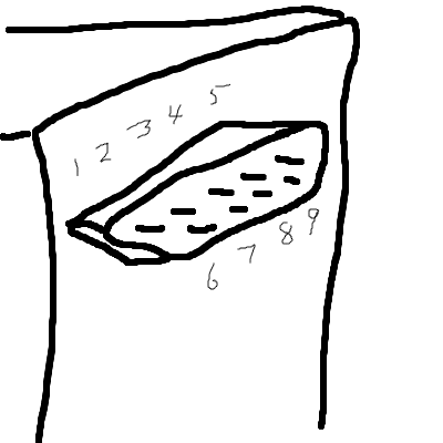
The following crude drawing... I will try to replace it one day!... is trying to show you a 9 way D plug on the back of a computer, the typical connector for the COM, or serial, port.
The top row has five pins, numbered 1-5 as shown, and the bottom row has four pins, 6-9.
The pin carrying "ground" is pin 5. The pin carrying data to the computer is pin 2, and the pin carrying data from the computer is pin 3.
Relative to the computer, pin 2 is the "receive" pin(Rx), an input, to the computer, and pin 3 is the "transmit" pin (Tx), an output from the computer.
If you are working on a system, and you want to do a test to see whether you have things confused, use a voltmeter. Read the voltage between the Tx pin and the ground pin, and the Rx pin and the ground pin.... if you are sure you have the right pin for the "ground" connection! If the port is "alive", and not connected to an external device, you will see a voltage on the output pin, possibly a negative voltage, and you won't see any significant voltage on the input pin. But check both the Tx pin and the Rx pin... you'd be surprised how often you'll either find zero on both, or a voltage on both... in which case there is probably something wrong with your "understanding" of what is going on!
BEWARE: Not every cable with a 9 way D socket on one end and a 9 way plug on the other is what it seems. You may, for instance, be holding a "null modem cable". Useful in it's place, but not good if you use it just to bring a device away from the back of your computer. (More on this later). For simple things, you want a "straight through" cable, and it doesn't even need to have more than pin/socket 2, 3 and 5 connected. Beware: Your cable may have connections, say, from pin 7 to pin 8 within the plug. (or socket). I.e. not every connection will go from one end of the cable to another, and some may go to more than one pin or socket.
For working with microprocessors, and many other jobs, you may want to convert from and to the "RS-232 voltage levels" used by your computer to "TTL", which is used by many... not all... microprocessors. ("TTL" implies more than just certain voltages, but the voltages are a major part of what it implies!) The Wulfden PA4B interface is one simple, inexpensive, solution. I have a separate page for you about the issues of RS-232 meaning more than just "serial", in particular the issues of voltage.
Speaking of links... the PA4B is very flexible... it may not be wired as shown below, but this was the standard set-up at 3/10, because it "plays nicely" with Arduinos like this.
The following crude drawing... I will try to replace it one day!... is trying to show you Wulfden PA4B interface, drawn oriented so that it is "the right way around" to plug into the serial port on the back of the computer in the first drawing.
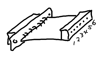
On the right hand edge (as drawn above) of the device there are six sockets. I have no idea what the "standard" numbering is of those sockets, but what I've used in the drawing is what I'm referring to below.
Connect the ground of whatever external serial device you are connecting to your computer via socket "1".
Feed 5 volts into the interface via socket "3"
Socket 2, if the links on your interface are as normal is connected to nothing.
Socket 4 is carrying the interface's serial data output... data from the PC's socket's pin 3 appears here, with the voltage levels shifted.
Socket 5 is an input to the interface. Connect the incoming (to the PC... outgoing from the device "to the right" (as the diagram is drawn) of the interface... signal here. The data will be passed on to pin 2 on the PC.
Socket 6 is for the Reset signal. I will have to get back to you on the details of this! Or visit the Wulfden site. It isn't important if you are just using the interface to connect an external serial device to your PC. It isn't complicated when you use it for what it is intended for... I just don't want to put anything here that isn't precisely right, and let you down.
The following table tells you where to find the three main connections on a 25 way D connector, and it tells you where some other signals are. I'll try to get around to writing them up one day. In the meantime, the following will at least tell you which are inputs, which are outputs. N.B.: As you can infer from the "input/ output" information for the Tx and Rx pins, this table is couched in terms relative to the COM port on a PC. Also note the neat little "gotcha" "they" built into things... the signal on pin 2 on a 9-way D is on pin 3 of a 25-way D, and vice versa. Sigh.
You have already been told about the ground connection and the Tx and Rx signals. The others are mostly for handshaking, although they get pressed into service for other jobs, too.
9-W    25-W   input
D pin  D pin  or    Name  Description
number number output
  1      8    in    DCD   Data carrier detect
  2      3    in    Rx    Received data
  3      2    out   Tx    Transmitted data
  4     20    out   DTR   Data Terminal Ready
  5      7    xx    Gnd   Received data
  6      6    in    DSR   Data Send Ready
  7      4    out   RTS   Request To Send
  8      5    in    CTS   Clear To Send
  9     22    in    RI    Ring indicator
Also for you, I have more general discussions of ports, serial and parallel, and of the fun of using the serial port to connect microprocessors to each other and to PCs.
If you visit 1&1's site from here, it helps me. They host my website, and I wouldn't put this link up for them if I wasn't happy with their service.![]()
![]() Page tested for compliance with INDUSTRY (not MS-only) standards, using the free, publicly accessible validator at validator.w3.org
Page tested for compliance with INDUSTRY (not MS-only) standards, using the free, publicly accessible validator at validator.w3.org
....... P a g e . . . E n d s .....