 Recommend to StumbleUpon
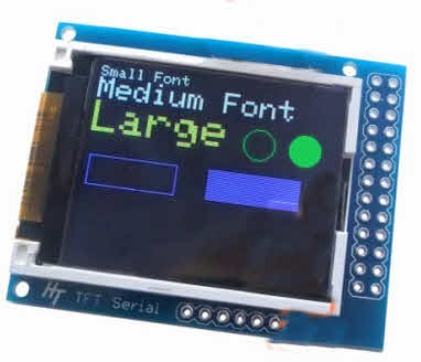
Great little device! Vivid colors, Crisp image. Very readable.
I speak of the Hobbytronics 1.8" TFT display with microSD socket, £24 inc VAT, but excl p&p, July 15... and still £24 at 10/17!
If you already have one, and have it hooked up, I have a separate page for your about putting text and graphics on a Hobbyboards serially connected 1.8 inch TFT display.
A SIMILAR device is available from Adafruit, $20, 7/15. N.B. I have not "played" with one of those. I don't know how it is hooked up. It uses the same display, so should have the same capabilities, and crisp, vivid display. It also has the microSD socket. But!!... I'm pretty sure it does not have the option of the simple "by serial" control. This means programming challenges for you, and also more complex wiring... using more pins. The mail between the UK and the US is pretty good, the device is small. I'd "go for" the Hobbytronics device, if I were you! (But it is a comfort to know that heavyweight Adafruit likes the sub-module it is built around.)
I have to qualify my endorsement with "it is early days". I haven't had mine long. But, in particular, I wanted to tell anyone looking at the Hobbytronics page: Don't be distracted or dismayed or dissuaded by the Adafruit libraries on offer. You don't need them! At least for Arduino use. (Or Pi, or BBC:MicroBit unless I am very much mistaken.) Neither should you be distracted by the illustrations showing "complex" connections to Arduino or Pi.
WHEN YOU GET YOUR TFT serial GRAPHICS/ SD CARD MODULE: Note the COLOR of the tab on the plastic protector which is on the face of the TFT screen. You may need to know what color that was, later. (There's no NEED to pull the plastic protector off. But if you want to, BE SURE to note the color of the tab!)
Further on the "tab" issue: My device came with a green tab. On a 1.8" display. Once upon a time, if you looked CLOSELY at the rems in the demo programs for the device, you saw that not only the color of your tab matters, but also the size of your display. If you have accessed an old demo program for the device, found in some obscure corner of the net, there may be a "tft.initR" routine, or equivalent. The tab color may be useful to you for getting the values at the tft.initR step precisely right for your unit... but, today (09 Oct 17) the demo at the Hobbytronics page doesn't seem to have tft.initR any more, so maybe it isn't needed with a recently purchased- from- Hobbytronics module.
Back to the Good News... You only need 3 wires! (Or four, if you want to use the reset line... but I don't think you need that.) That's the hardware. (More help given in a moment.)
For software, use what's in the "Example Arduino Sketch" under "Examples" under "Documents".
That's BORING!... but... it makes a good starting point.
Nota Bene: The following is set up for a system where D2 is not being used, and data to display flowing over D3
#include <SoftwareSerial.h>
SoftwareSerial mySerial(2,3); // RX, TX

void setup() {
  mySerial.begin(9600);
  delay(500);
}

void loop() {
  mySerial.println("Hello world ");
  delay(600);
}
The above is a complete program for the display
If you just want to display text, that's "all" you need. (You will, however, find that some "logical" lines of the screen are off the bottom of the "physical" screen, in the default mode. Learning to do more with the commands available will be worth your while. But even without the commands, you can get by. If you were to do a loop, sendig 1,2,3,4... etc to the screen, each with a println, so that each next number appeared a new line, you would get the expected 1,2,3,4,5,6,7,8... and then the device would seem to seize up! If you were sending the lines one- per- second, there would be a 8 secind delay, while 9,10,...16 were "printed in the air", "below" the screen. At that point, the LOGICAL screen would be full, and the write- to- screen would wrap, and "17" would appear in the top line, then 18 on the next, and so on. (If you learn to use the commands, you can change the font size, and all 16 lines fit on the screen, or, more likely the way forward, you can tell the display where each scrap of text should go by issuing a "go to text posn x/y just before each print command. (Is it "way forward", or "way backward".... "When I was a boy...", all we had was character oriented displays. (Actually, when I was a boy all we had was character oriented ink-on-paper displays. You could go right or down, never left or up! (Actually, you COULD backspace on "fancy" displays. But I digress? You CAN survive with JUST print and println. But why restrict yourself? Doing the command is NOT hard.)
You can have different font sizes, and colors (262,144 shades.. in displayed bitmaps. Only 8 (incl black) in text/ graphics) and graphics if you use the commands explained in the table on the Hobbytronics page. It really isn't hard, especially if you use the subroutines provided for you in the example sketch.
We'll come back to being fancy in a moment, but first let's get the display hooked up, and do the simple text writing...
Wiring: From the six pad set on the same edge as the SD socket... Run wires from "5v" "Gnd" to the Arduino's, and a wire from the pad marked RX on the display to D0 to use the example sketch. (For just a little more trouble, in the software only, you can use a different pin on the Arduino as the source of your serial data... and avoid the pin that is part of the programming of the Arduino and its serial monitor.
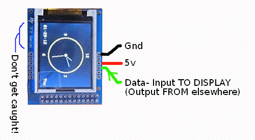
(The "Don't Get Caught" warning is for the following: The module is the HobbyTronics' ("HT") TFT Serial module. The label with the module's name was, unfortunately, placed next to the module's programming pads. The pads for the serial interface are the other set of six, the one's on the right hand side, in the illustration opposite.
The green wire goes to the MODULE's "Rx". In other words, the pad through which the MODULE will RECEIVE the data to control it. I've made such a fuss about "THE MODULE will receive", because for many newbies herein lies an opportunity for confusion. The wire will come FROM an OUTPUT of the Arduino (or Pi, or whatever you want to use to control the display), because it is going to an INPUT on the display. Outputs feed inputs! DO NOT connect the output of one device to an output of another, except in very special circumstances. Input-to-input will (probably) do no harm... but it won't be much use! (Again, except in special circumstances.) Inputs go to outputs. Outputs go to inputs... when you use pad names predicated on the device they are part of.
START SIDEBAR... that, again, in detail...
Starting from the pad nearest the SD card carrier...
I soldered a black wire to pad "1", marked "GND", the left hand-est one. For the ground connection.
Skipped pad "2", (had no text on silkscreen on board.)
Soldered a red wire to pad "3", marked "5v". For the 5v from other parts of my circuit, the Arduino.
Soldered a green wire to pad "4", marked "Rx". For the data to the display.
Skipped a pad "5", marked "Tx". (Would be for data FROM display.)
(Optional... leave this off, if access will be easy later. At least make the wire short, if you intend to let it float. DO NOT connect to 5v... it is the reset line to a 3v3 Atmel... Do not connect to 5v unless you know that would be okay. I doubt it would be. However, don't worry: The data line can be run at 5v.) Soldered a yellow wire to pad "6", marked "/Res". For the reset signal, should I find I need to use it. (Pull that pad low briefly, and then let it float again to reset the device. (Signal is pulled up by a resistor on the board.)
... END SIDEBAR
That's it, for hooking up. The "Hello World" program (above) should run on that. Get that much working before moving on.
Before I forget... the colors are as follows, if you are using one of the built in commands to, say, set the foreground color....
    0 BLACK
    1 BLUE
    2 RED
    3 GREEN
    4 CYAN
    5 MAGENTA
    6 YELLOW
    7 WHITE
If you entered the little "Hello world" program above, replace it with the Hobbytronics demo, "Arduino Example Sketch". But modify it as described in a moment.
Before I give you the tweaks (mostly to reflect the wiring I've suggested), a word about something that may confuse/ worry you.
In the Hobbytronics code, you'll see that it seems that void tft_command() has been defined five times! Odd, if you don't know about "overloading".
If you look closely at the definitions, you'll see that, yes, they all start "void tft_command("... but then each has a different parameter list.
If you call tft_command('X'), the first version of tft_command() is used. If you call tft_command('X','Y'), the second version of tft_command() is used. The system knows which version to use by what parameters are supplied.
This is an example of overloading, which I have written a short page about, if the above doesn't suffice.
Include all five of the tft_command() definitions in your code, just to have them in place, should you add something to your program which needs one of them.
Right... back to what I was saying...
Do the following to the Hobbytronics code to make it run with the same wiring as you used above. The tweaks are just to avoiding using D0. I avoid it because it is used for programming the Arduino, and for the useful system-provided Arduino serial monitor
Start by using the editor's "Find" (and replace) to change all instances of Serial to mySerial.
Then put...
#include <SoftwareSerial.h>
SoftwareSerial mySerial(2,3); // RX, TX
... near the top of your program (sketch). I've use "2,3" which would allocate pin D2 for the software serial's receive line (you won't be using it. I'm pretty sure you can use it for other INPUT uses, even though the software serial is also "using" it.)... AND allocate D3 for the line data will be sent on. (You can, of course, choose to use different lines.)
If you didn't already do so, connect the display's Rx to D3, if you used the numbers I did.
Have a close look at what you know about your display, and the
For now, rem out the line that says...
tft_command(13,120,85,"rpi2.bmp");
That should do it! Run the program! You should get...
... but with nicer colors, and CRISP!)
There are commands to set background and foreground colors, clear the screen, change font size, go where you wish on the screen to put a letter (or letters).
You can also "goto" a position specified by the underlying grid of physical pixels. (That's a separate command from the "get ready to put text at...") Once there, you can draw lines to other places... though I can find no reason to do so! There is no "read pixel", or "do dot at current pixel" or "draw from current pixel" command.
If you want to set the color of a single pixel, you do it by drawing a line from the pixel's location to the pixel's location! (The code for draw line is 8, so to set the pixel at 10,20, you use tft_command(8,10,20,10,20); (Set the foreground color before calling the "draw (very short, this time!) line".
I've prepared a separate page covering commands to write text and draw graphics on this ST7735 TFT display.
Once you have a memory card in the microSD socket, with a .bmp file called MyImage.bmp already saved on it (see below for more on that), you can, adapted as below, use the line in the demo that (nearly) says...
tft_command(13,120,85,"MyImage.bmp");
Note: You do NOT have to use an SD card at all. You an send text and graphics to the display over the serial connection already discussed. The "doing" of that (the software), I will discuss in a moment. An alternative way to get a display on the screen is as follows....
I've created a separate page with the details of using the SD card of the Hobbytronics TFT display.
(I presume... but I haven't tried it... that you can have several bitmaps on the SD card, and use them as you wish.)
I'm told you can also write data to the card.
Love this little display!
"And another thing", as the great Jeremy Clarkson was wont to say: Do you have a "big" PC, running all the time, but doing some task that doesn't warrant having a big display running 24x7 also? Stick one of these on a serial port! (You may have to do some level shifting/ inverting... but that's not hard.) (I suspect you could interface it easily with the sort of cable/ interface used for programming Arduinos which don't have built in USB interfaces.)
For a mere $35 or so, this is just too much fun... and so useful... not to "rush out", buy one, try it for yourself.
I have only scratched the surface. (Of the topic. Happily, my display remains pristine.) There are good videos to show you the splendid results which are possible. Plus, I hope you will enjoy trying things in the commands table, which I believe is comprehensive.
Just in case it is easier for you, or in case the "master" copy of the following falls off the web...
Here are the subroutines which make working with the device on an Arduino easy. (Source, thank you: HobbyTronics.co.uk
// ------------------------------------------------------
// Overloaded tft_command functions (to make life easier)
// ------------------------------------------------------
void tft_command(unsigned char cmd)
{
  Serial.write(0x1B);
  Serial.write(cmd);
  Serial.write(0xFF);
}
void tft_command(unsigned char cmd, unsigned char param1)
{
  Serial.write(0x1B);
  Serial.write(cmd);
  Serial.write(param1);
  Serial.write(0xFF);
}
void tft_command(unsigned char cmd, unsigned char param1, unsigned char param2, unsigned char param3)
{
  Serial.write(0x1B);
  Serial.write(cmd);
  Serial.write(param1);
  Serial.write(param2);
  Serial.write(param3);
  Serial.write(0xFF);
}
void tft_command(unsigned char cmd, unsigned char param1, unsigned char param2, unsigned char param3, unsigned char param4)
{
  Serial.write(0x1B);
  Serial.write(cmd);
  Serial.write(param1);
  Serial.write(param2);
  Serial.write(param3);
  Serial.write(param4);
  Serial.write(0xFF);
}
void tft_command(unsigned char cmd, unsigned char param1, unsigned char param2, const char str[])
{
  Serial.write(0x1B);
  Serial.write(cmd);
  Serial.write(param1);
  Serial.write(param2);
  Serial.write(str);
  Serial.write(0xFF);
}
![]() Page tested for compliance with INDUSTRY (not MS-only) standards, using the free, publicly accessible validator at validator.w3.org
Page tested for compliance with INDUSTRY (not MS-only) standards, using the free, publicly accessible validator at validator.w3.org
....... P a g e . . . E n d s .....